GENERAL SYSTEM DIAGNOSTICS SERVICE MANUAL NUMBER 23
Page 5E-92 90-861326--1 MARCH 1999
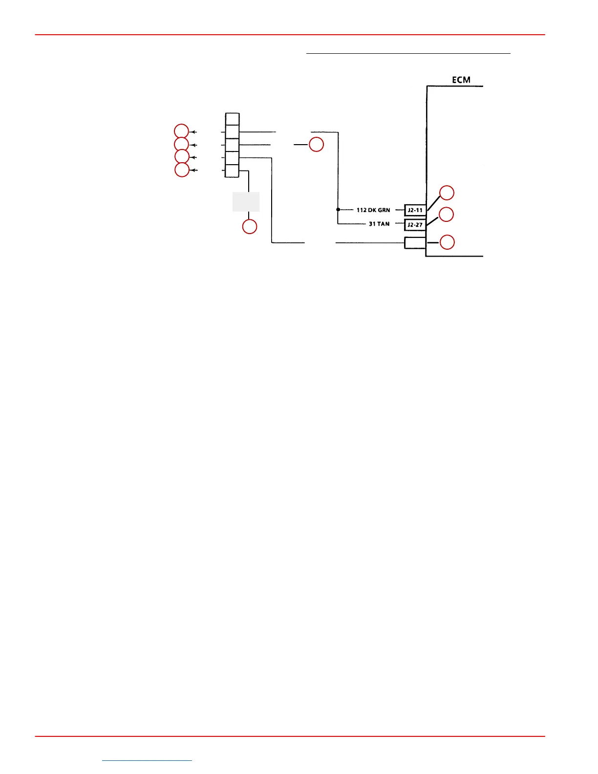
Discrete Input Circuit Check - Non-Scan - 454 / 502 Mag MPI and 8.2L MPI Only
(1 of 5)
931
BRN
J1-6
121 TAN
3 PNK
TAN/
BLU
BLU/
TAN
GRY
D
PUR
C
B
A
121
WHT
a
b
c
d
e
f
g
h
i
a-To Buzzer
b-To Ignition
c-To Audio Warning Switches
d-To Tach
e-To System Relay Term “87”
f-To Ignition Coil
g-Coolant Overtemp (To Buzzer)
h-Low Oil Pressure/ Low I/O Fluid (To Buzzer) (Trans. Temp. MIE)
i-To Low Oil Pressure And Gear Lube Switches (Trans. Temp. MIE)
CIRCUIT DESCRIPTION:
Several discrete switch inputs are utilized by the fuel injection system to identify abnormal
conditions that may affect engine operation. A pull-up switch is currently used in conjunction
with the ECM to detect critical conditions to engine operation.
If a discrete switch changes states from its normal at-rest position, that is normally open to
closed (or closed to open), the ECM senses a change in voltage and responds by activating
the audio warning system.
TEST DESCRIPTION:
A problem with the discrete circuit system will have to be broken down into several sub-
steps. These will include the following:
• Testing the audio warning buzzer.
• Testing the individual switches.
• Testing the wiring.
Be sure that all items above have been performed prior to replacement of the ECM.
DIAGNOSTIC AIDS:
• Check engine oil and gear lube levels. Check transmission fluid for overheat condition.
An intermittent problem may be caused by a poor or corroded connection, rubbed through
wire connection, or a wire that is broken inside the insulation.
Downloaded from https://needmanual.com/!
 Loading...