GENERAL SYSTEM DIAGNOSTICS SERVICE MANUAL NUMBER 23
Page 5E-98 90-861326--1 MARCH 1999
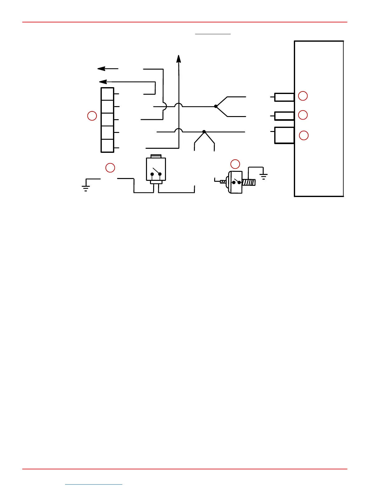
Discrete Input Circuit Check - Non-Scan - 7.4L MPI Only (1 of 5)
J2-11
J2-26
J1-4
E
D
C
B
A
121 WHT
112 GRY
31 TAN
931 BRN
3 PNK
585 TAN/WHT
3 PNK
31A DK GRN
DK BLU
906 TAN/WHT
114 PUR
or
J1-6
BLK
a
b
c
d
e
f
a-Harness Connector
b-Gear Lube Switch
c-Oil Pressure Switch
d-Coolant Over Temperature & Discrete Switch Output
e-Not Used
f-Discrete Switch Input (J1-4 For Earlier Models And J1-6 For Earlier And J1-6
For Later Models)
CIRCUIT DESCRIPTION:
Several discrete switch inputs are utilized by the fuel injection system to identify abnormal
conditions that may affect engine operation. A pull-up switch is currently used in conjunction
with the ECM to detect critical conditions to engine operation.
If a discrete switch changes states from its normal at-rest position, that is normally open to
closed (or closed to open), the ECM senses a change in voltage and responds by activating
the audio warning system.
TEST DESCRIPTION:
A problem with the discrete circuit system will have to be broken down into several sub-
steps. These will include the following:
• Testing the audio warning buzzer.
• Testing the individual switches.
• Testing the wiring.
Be sure that all items above have been performed prior to replacement of the ECM.
DIAGNOSTIC AIDS:
• Check engine oil and gear lube levels. Check transmission fluid for overheat condition.
An intermittent problem may be caused by a poor or corroded connection, rubbed through
wire connection, or a wire that is broken inside the insulation.
Downloaded from https://needmanual.com/!
 Loading...