SERVICE MANUAL NUMBER 23TROUBLE CODE DIAGNOSTICS - 454/502 MAG MPI & 8.2L MPI
Page 5F-18 90-861326--1 MARCH 1999
Code 43 (2 of 3): Knock Sensor (KS) Circuit (Non-Scan)
Step 5. This step confirms the ability of the KS module to remove the voltage from the signal
line when it sees spark knock. Since the knock sensor produces an AC voltage signal, it may
be necessary to repeatedly touch the harness connector with the test light probe to simulate
this type of signal.
Step 6. This step checks the ground circuit from the KS module. If the test light is dim, check
ground (CKT 486) for excessive resistance.
Step 7. This step determines if ignition voltage is available to power up the KS module.
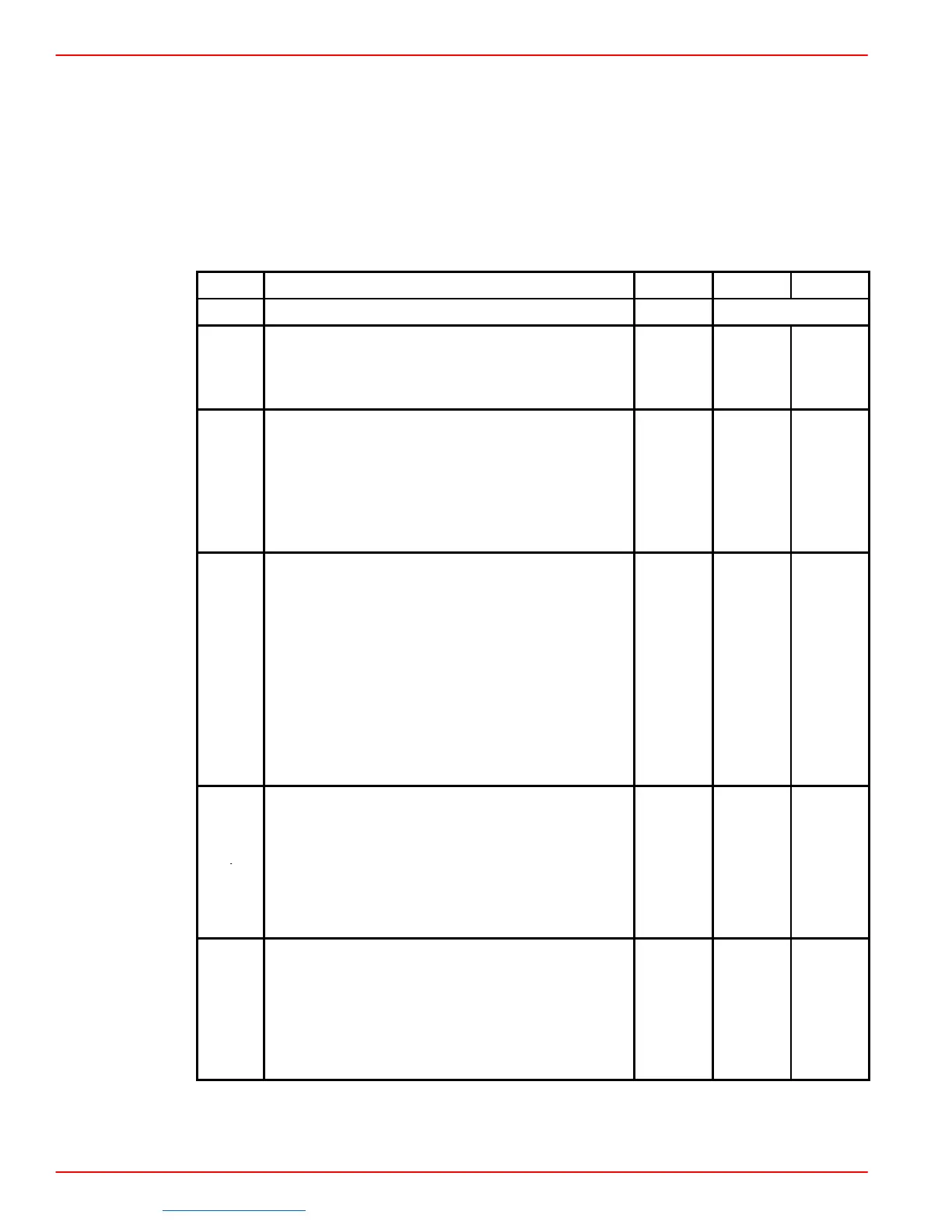
STEP
ACTION VALUE YES NO
PROCEED TO
1
Was the “On-Board Diagnostic” (OBD) System
Check Performed?
– Step 2
Go to
OBD
System
Check
1. Disconnect 5-way KS module connector.
2. Using DVOM, measure resistance be-
tween terminal “E” and ground.
3.3K to
3. Resistance should be between 3.3K and
4.5K Ohms.
.
Ohms
Is it?
Step 3 Step 9
1. Reconnect 5-way KS module connector.
Disconnect knock sensor harness connector.
2. Connector a test light to battery positive
battery positive (B+).
3. Start engine.
4. Hold engine speed steady at 2500 rpm.
5. Repeatedly touch test light to knock sen-
sor harness connector terminal (CKT 496).
Does a noticeable rpm drop occur, or using
timing light, did timing drop?
– Step 8 Step 4
1. Ignition OFF.
2. Disconnect ECM J-1 connector.
4
3. Ignition ON.
4. Connect DVOM from ECM connector ter-
minal “J1-1” (CKT 485) to ground.
Are 8-10 volts present?
– Step 5 Step 7
1. Allow DVOM voltage to stabilize.
2. Connect a test light to battery positive
(B+).
3. Touch test light to knock sensor connec-
tor terminal (CKT 496).
Does voltage value change?
– Step 14 Step 6
Downloaded from https://needmanual.com/!
 Loading...