Messenger Modem
®
Page 17
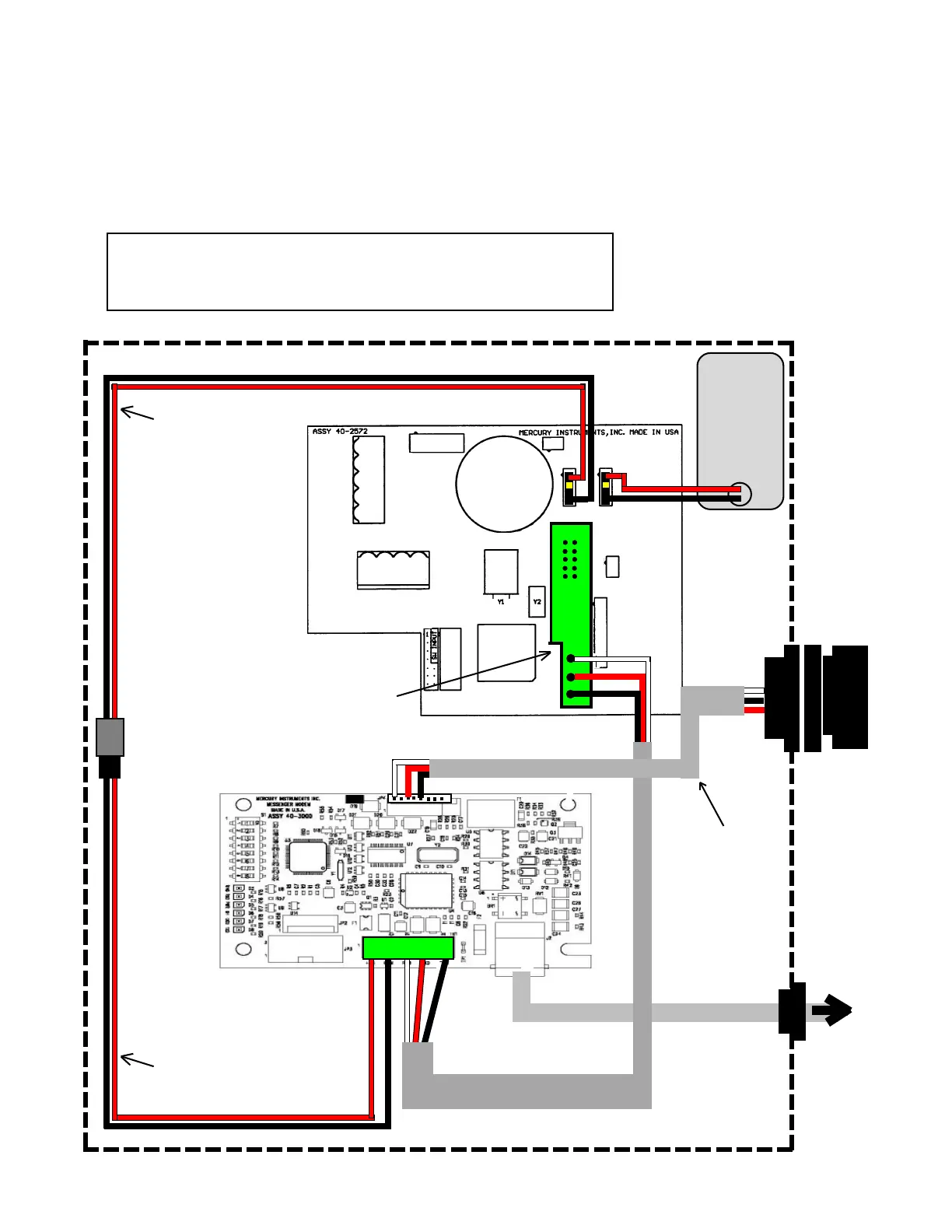
Messenger Modem Wiring Diagram
internal modem, CMOS to RS-232 converter Bd. w/ ext. case connector
for:
Mini-Max, Mini-Max AT, Mini-Max ATX, Sentry, Sentry X, ERX and Pulse Accumulator
J3
J4
J5
JP3
TB1
J2
Messenger Modem
Board p/n 40-3000
Mini-Max Board p/n 40-2572-xx
Power Disconnect
Cable
40-2876
(Not used in Pulse
Accumulator)
Power Cable
40-2820-5
Notes:
1. Set baud rate in instrument to 2400 at item 126
2. Set Communication Delays to 25 seconds at items 171 & 172
CMOS to RS-232
Converter Bd and
Cable Assy.
To
telephone
line
4 CELL
Alkaline
Battery
Pack
40-2596
or
40-2595
Dust
Cap
NOTE: Unplug the CMOS to RS-232 converter
board from main board J5 prior to plugging in
the MPA when attempting firmware upgrades.
JP4
TxD RxD COM
Serial Pass-Thru
Cable Assy.
40-4916


 To Next Page