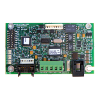
Messenger Modem Board
Parts Identification
2 Switch Configuration, from Top to Bottom (8 total):
(Note: OFF position is toward edge of board)
Switch Positions
OFF ON
Sw#1 - Baud Rate, 1200 2400
Sw#2 - Line Share / Line Surrender enable disable
Sw#3 - Answer Incoming Calls enable disable
Sw#4 - Wake-up on 1 Ring S0 Rings (default 9)
Sw#5 - Wake-up on Serial Data, enable disable
Sw#6 - Unused
Sw#7 - Configuration Mode enabled disable
Sw#8 - Serial Data Mode, RS-232 CMOS
When Switch 4 is set to ‘On’ the number of rings the modem will wake on is controlled
by the value of S0. The default value for S0 is 9, but it may be easily changed using the
Messenger Modem Configuration Software (see Appendix C)
When Switch 7 is set to “Off” the unit will go into configuration mode until the switch is
changed back or 10 minutes has passed. If the unit timed out with the switch in the
“Off” position it will automatically disable the configuration mode. To put the unit back
into conguration mode it is necessary to Move switch 7 to “ON”, Wake the Modem, and
move switch 7 back to the “Off” position.
Page 9
3 JP3 - Connector (2x5-pins) for CMOS-level serial data
from any of the Mini-Max family of main boards
4 JP2 - Connector (6-pins) sometimes used as a power
connection to the modem board
5 TB1 - Terminal Strip (5-lug) connections,
(assigned functions, left to right:)
+DC COM TXD RXD COM
6 J2 - Connector (RJ-11) telephone line connection
7 JP4 - Connector (8 pin) RS232 Communication and Configuration
 Loading...