Do you have a question about the Merlin Gerin Masterpact MP and is the answer not in the manual?
Details compliance with major international and marine standards.
Lists standard and high interrupting ratings for various models.
Ensures fast closing/opening via stored energy mechanism for reliable operation.
Accessories easily installed in the field without losing listing marks.
Reduced parts enhance reliability; no maintenance needed under normal conditions.
Easy front access to accessory terminals for inspection and modification.
Segregated compartment and reinforced insulation enhance safety.
Mechanical indicator confirms true contact status for safe isolation.
Racking handle access via door cutout for safe disconnection.
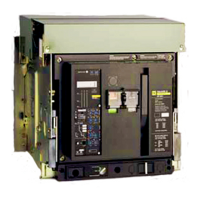
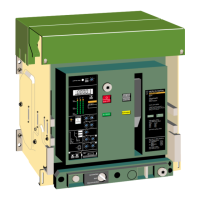
Lists major parts like terminal covers, arc chutes, motors, coils, and control units.
Identifies push buttons, status indicators, and locks on the front panel.
Labels for drawout position, fault indicators, and reset buttons.
Details the ST 208D control unit for general use, including protection features.
Describes long-time, instantaneous settings, and test receptacle functionality.
Explains how fault indicators, control voltage, and display work.
Details functions like fault indication, ammeter, and overcurrent/ground fault protection.
Specifies pickup and delay band settings for ground fault protection.
Describes inverse time pickup and alarm functions for load monitoring.
Covers fault differentiation, alarm indication, and built-in ammeter features.
Details functions like fault indication, ammeter, and overcurrent/ground fault protection.
Lists current setting, delay bands, and instantaneous pickup for overcurrent protection.
Covers ground fault pickup/delay and load monitoring functions.
Explains fault indication, alarm, and built-in ammeter features.
Describes using an external neutral sensor for 304W circuits.
Explains how ZSI provides selectivity by coordinating trip signals between breakers.
Provides two independent static contacts for load shedding and alarms based on current limits.
Differentiates trip causes using LEDs and opto-decoupled outputs.
Alarm indicates when long time pickup is exceeded before tripping.
Details configurations for reliable and interruptible control voltage.
Ammeter avoids external CTs, offers phase selection and easy reading.
Step-by-step guide for testing overcurrent protection with the mini test kit.
Detailed procedure for testing with the portable test kit, including safety precautions.
Safety warnings for test kit usage and table of maximum tripping times.
Connection via one or two plugs for fixed installations.
Terminal block wired to a separate block for automatic isolation in disconnected position.
Details screwless terminals and cable strip length for accessory connections.
Motor automatically charges mechanism for O-C-O cycles without recharging.
Releases closing mechanism when spring is charged; includes anti-pumping function.
Counts breaker cycles and describes the 'spring charged' switch functionality.
Rated for continuous duty, operates with control voltages, and can be used for ground fault protection.
Opens breaker when supply voltage drops below 35-70% of rated value.
Includes adjustable time delay to prevent tripping from transient voltage drops.
Describes possible combinations of shunt and undervoltage trip devices.
Switches for insulation of auxiliary circuits or standard operations.
Provides alarm/lockout information, operated when breaker is tripped.
Indicates breaker is ready to close, conditions must be met.
External plate with 24 SPDT switches, operated by cable.
Block of 4 SPDT switches operated close to the connected position.
Block of 2 SPDT switches operated close to the fully disconnected position.
Single SPDT switch operated only in the test position.
Table detailing current ratings for various switch types and voltages.
Shows operating diagrams for main contacts and OF auxiliary switches.
Illustrates diagrams for main and secondary disconnect positions with isolation distances.
Shows operating diagrams for CE, CD, and CT position switches.
Displays operating diagrams for the 24 additional auxiliary switches.
Devices to prevent manual operation and lock breaker in open state.
Mechanisms to prevent door opening or racking when the breaker is in specific positions.
Allows securing the breaker in the disconnected state.
Ensures breaker tripping before disconnection and prevents closing if incompletely connected.
Covers priority of opening orders, fault indicators, and anti-pumping function.
Describes mechanical interlocking between stacked or side-by-side breakers using rods or cables.
Illustrates mounting arrangements for three stacked breakers with different power supplies.
Details interlocking options for two side-by-side breakers.
Shutters block access to main disconnects in disconnected, test, or withdrawn positions.
Ensures correct breaker-cradle assembly matching via 20 combinations.
Prevents arc prolongation and isolates connections in bus bar installations.
Hinged cover for enhanced protection on door escutcheon.
Shows time-current curves for long time and instantaneous pickup settings.
Table listing interrupting ratings for various models.
Table detailing instantaneous pickup values for various models.
Displays time-current curves for long time and short time pickup settings.
Lists interrupting ratings for standard and high configurations.
Details instantaneous pickup values for various models.
Shows time-current curves for long time and short time pickup settings.
Lists interrupting ratings for standard and high configurations.
Displays time-current curves for long time, short time, and instantaneous pickup.
Lists interrupting ratings for various models.
Details instantaneous pickup values for different models.
Displays time-current curves for long time, short time, and instantaneous pickup.
Lists interrupting ratings for various models.
Time-current curves for ground fault protection settings.
Details ground fault pickup values based on sensor rating and breaker model.
Time-current curves illustrating load monitoring functions Ic1 and Ic2.
Explains load limit settings for monitoring and alarm functions.
Wiring diagrams for connected and disconnected position switches.
Wiring diagrams for undervoltage trip, shunt trip, closing coil, and motor operator.
Wiring diagrams for standard, heavy duty, and other auxiliary switches.
Wiring for ammeter, local/remote fault indications, and zone-selective interlocking.
Diagrams for ground fault protection and load monitoring options.
Wiring diagram for communication output through Dialpact system.
Important notes on terminal availability, ZSI, communication, and power supply requirements.
Dimensions for drawout and fixed mounting door cutouts and drilling.
Dimensions for mounting the external neutral sensor.
Specifies dimensions for the rear cutout.
Mounting dimensions for MP30 and MP40 breakers.
Dimensions for fixed mounting of MP08-MP16 breakers.
Dimensions for drawout mounting of MP08-MP16 breakers.
Specifies dimensions for insulated cells and cubicle space requirements.
Dimensions related to withdrawn and disconnected positions.
Dimensions for fixed mounting of MP20 breaker.
Dimensions for drawout mounting of MP20 breaker.
Specifies dimensions for insulated cells and cubicle space requirements.
Dimensions related to withdrawn and disconnected positions.
Dimensions for fixed mounting of MP25-MP30 breakers.
Dimensions for drawout mounting of MP25-MP30 breakers.
Details required cubicle space and ventilation for drawout mounting.
Detailed dimensions for drawout mounting of MP40 breaker.
Detailed dimensions for drawout mounting of MP50/MC50 breakers.
Specifies cell requirements and cubicle space for drawout mounting.
Details switch ratings and short-circuit withstand when protected by a circuit breaker.
Describes switch design, lack of overcurrent protection, and safety caution.
Refers to breaker details for accessories, dimensions, and connections.
Suggests periodic inspections six months after installation and annually thereafter.
Guides for checking terminal tightness and main contact wear.
Procedures for removing dust/dirt and periodic breaker operation.
Describes how to perform insulation resistance tests under severe operating conditions.
Tables detailing mechanical and electrical endurance without maintenance.
Endurance figures achievable with service maintenance.
Tables showing endurance requirements from UL489 and ANSI standards.
Explains that endurance values are based on normal conditions and conventional tests.
Details compliance with UL489 and IEC 947-2 standards.
Lists standards for auxiliary and position switches.
Details standards and voltage ratings for motors, coils, and trip devices.
Optimizes cable/bus bar protection for repetitive faults by adjusting time delay.
Remembers and integrates thermal heating, reducing time delay and affecting reclosing.
STR 38S and 58U units incorporate thermal memory for protection.
Caution regarding the use of the "min" position for reclosing on fault.
| Standards | IEC 60947-2 |
|---|---|
| Poles | 3 or 4 poles |
| Trip Unit Type | Electronic |
| Mounting | Fixed, Drawout |
| Protection Functions | Overload, short-circuit, ground fault |
| Communication Options | Modbus, Ethernet |