Turn off electrical power supply
b
efore servicing. Contact with live electric compo-
n
ents can cause shock or death.
All electrical and control wiring must be installed in
accordance with the codes listed in Section 1 of this
manual. Standard wiring diagram is provided in Figure
2.9. Optional wiring diagrams are provided in Figures
2.10-2.13. A separate 230/1/60 power supply is
recommended for the unit. Use standard 15-amp fuse and
14-gauge wire from power supply to unit.
Connect power supply to Terminals L1 and L 2 on the
high voltage terminal block. Connect a ground wire to the
equipment ground terminal located next to the high volt-
age terminal block.
10
STEP 7: WIRING THE UNIT
Locate the room thermostat on a wall near the return air
box, between 40" to 48" from the floor. Connect the low-
voltage thermostat wiring from the room thermostat to the
low voltage control block in the unit.
Connect low voltage from fan coil unit to condensing unit
as shown in Figure 2.9.
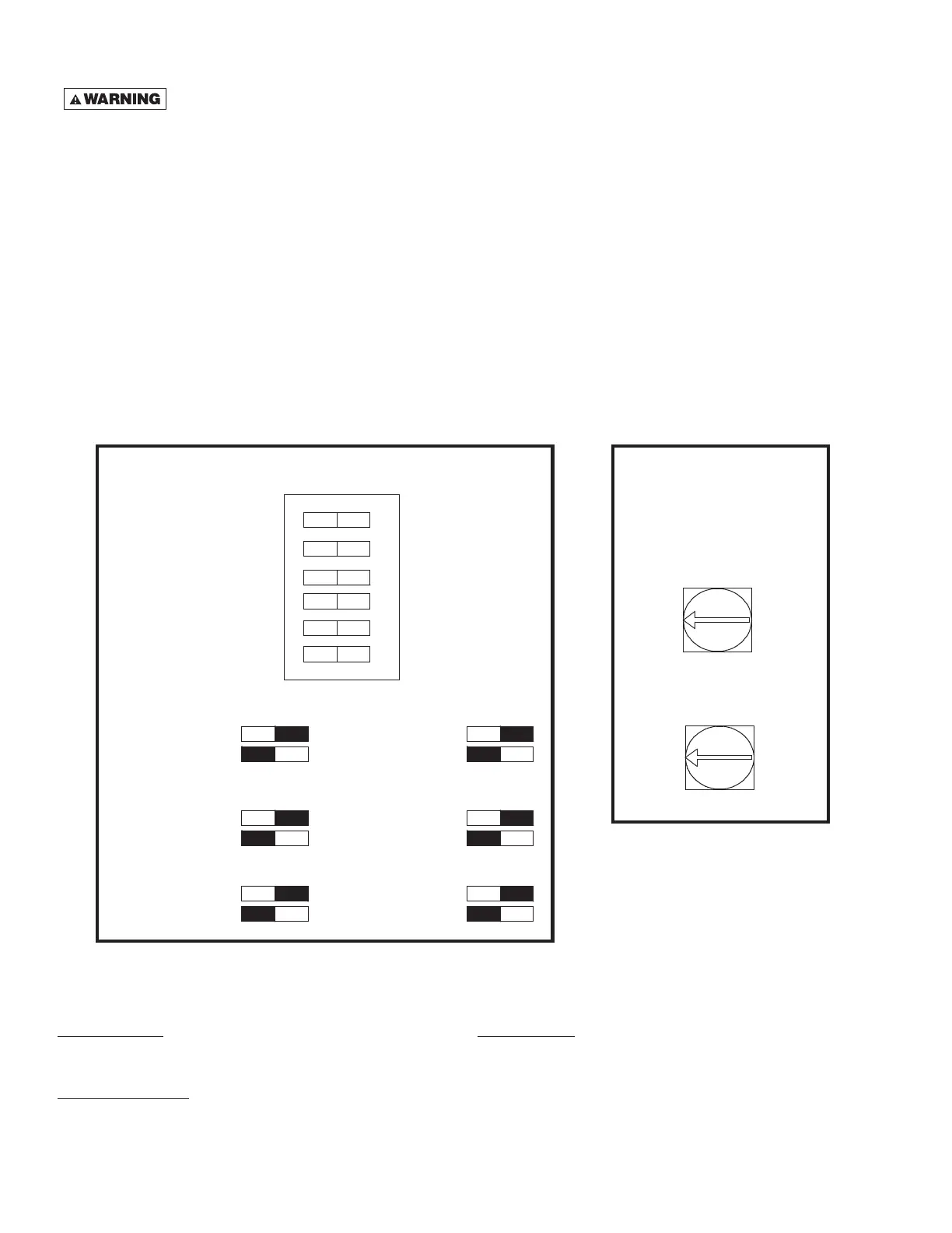
Set DIP switches according to application. See
SpacePak J Series Control DIP switch settings below.
Alternately, the unit may be configured to run on
115V, 60 Hz power. Refer to kit WG0858 for instruc-
tions and material to convert from 230V to 115V
shipped with the unit.
C
WC
HWC
HP
O
B
P
W
C
F
C
Cooling Water Coil Present
Cooling Water Coil Settings
Switch 1
N
o Cooling Water Coil Present
H
eat Pump Present
Heat Pump Settings
Switch 3
No Heat Pump Present
ON
Potable Water Circulation Settings
Switch 5
OFF
Heating Water Coil Present
Heating Water Coil Settings
Switch 2
N
o Heating Water Coil Present
Energized in Cooling Mode
Changeover Valve Settings
Switch 4
Energized in Heating Mode
ON
Two Stage Cooling Settings
Switch 6
OFF
SpacePak J Series Control Dip Switch Settings
Fan On Delay for
W
ater Coil Heat Demands
Adjustable from
0
- 5 Minutes
SpacePak J Series
Control Variable
Time Delay Settings
0
5
F
an Off Delay for ALL
H
eating and Cooling Cycles
Adjustable from
0 - 5 Minutes
0
5
Power Indicator
The Power indicator will blink to indicate that the control is
operational.
Fan Prove Indicator
The Fan Prove indicator will illuminate when there is power to
the fan.
Note: The Fan Prove Terminal will also energize with 24VAC when
the above conditions are met.
CONTROL DIP SWITCH SETTINGS
CONTROL VARIABLE
TIME DELAY SETTINGS
Fault Indicator
Fault Flash Codes:
Float Switch 1 Flash
Anti-Frost Switch 2 Flashes
Fan Prove Fault 3 Flashes
Note: All Flash Codes are latched until power is cycled, even if the
fault is cleared. The Float Switch requires power to be cycled to
resume operation.
SpacePak J Series Control Indicator LEDs
 Loading...