STEP 8: INSTALLING AIR DISTRIBUTION COMPONENTS
All plenum duct and supply tubing runs as well as room
terminator locations must be in accordance with air
distribution system requirements listed in Section 1 of
this manual. Use a tape that meets UL181 requirements
on all joints.
Plenum Duct Installation
All tees, elbows and branch runs must be a minimum of
24" from the fan coil unit or any other tee, elbow or branch
run. Keep all tees and elbows to a minimum to keep
system pressure drop on larger layouts to a minimum.
NOTICE: Refer to duct installation instructions sup-
plied with fan coil unit or follow manufacturers
instructions supplied with other duct system types.
Room Terminator & Sound Attenuating
Tubing Installation
Room terminators and pre-assembled sound attenuating
tubes are provided in the Installation Kits.
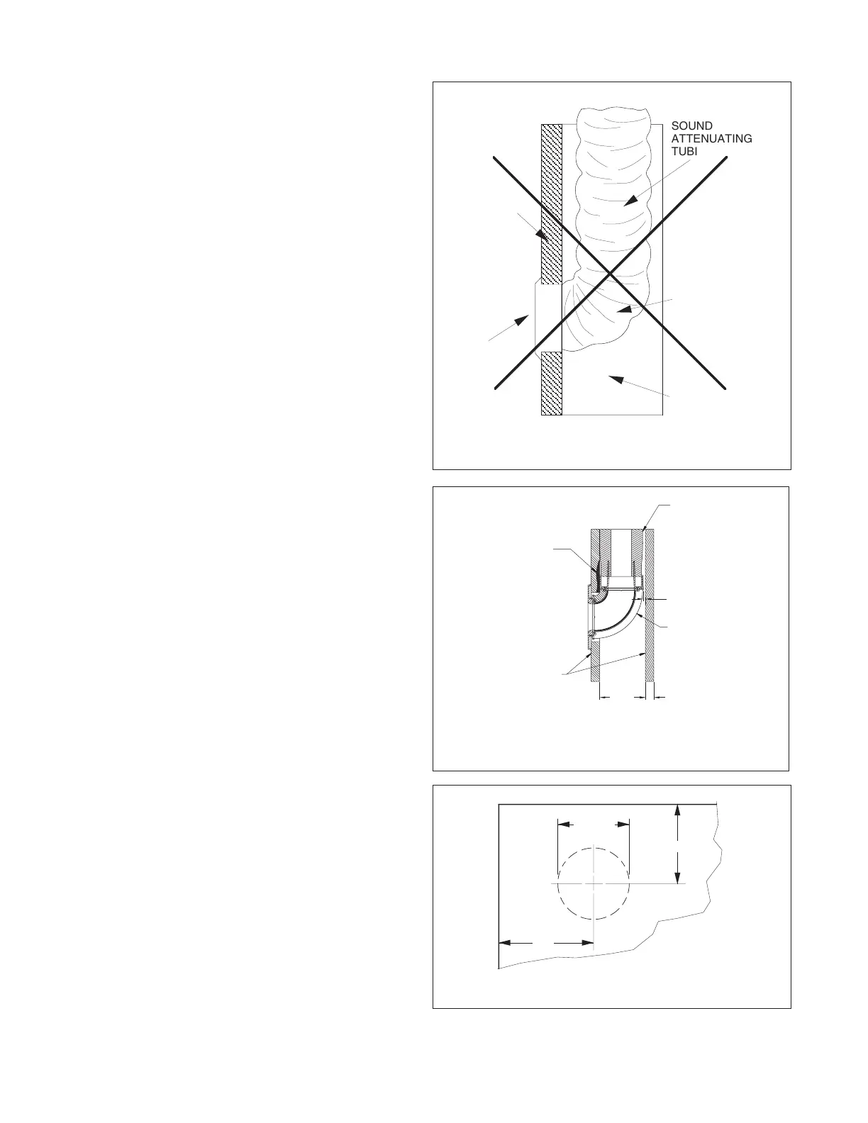
NOTICE: Do not install terminators in a wall in
which a sharp bend in the sound attenuating tube
is required (see Figure 2.14). The result would be
unacceptable noise
.
OPTION: Using a SpacePak Kwik Connect Wall Elbow
(Model Number: AC-KCWE) addresses this condition
(see Figure 2.15).
In marking location for room terminator (see Figure 2.16),
the center of the terminator should be approximately 5"
from the wall or, when installed in the corner of a room 5"
from both walls.
After marking location, drill a 1/8" diameter hole for outlet.
Verify there is at least 2" for tubing assembly clearance all
around this hole by visual inspection or inserting a bent
piece of wire to feel for obstructions. Adjust direction of
hole as needed, to gain this 2" clearance. After all
clearances have been checked, take a 4" diameter rotary-
type hole saw and cut a hole, using the 1/8" diameter hole
as a pilot.
Assemble spring clips to terminator plate with screws
provided in installation kit. Tighten clips until they are
close to the thickness of the material they are being
mounted to.
Assemble the room terminator to the sound attenuating
tubing by simply fitting the two pieces together and
twisting until tight (see Figure 2.17). If the terminator is to
be used in a floor location, then field fabricate a small
screen (1-1/2" square; 1/4 x 1/4 20-gauge galvanized wire
screen) and place screen over opening on the back of the
terminator prior to twisting on the kwik-connect (on the
sound attenuating tube).
16
SOUND
ATTENUATING
TUBING
THIS RADIUS
TOO SHORT
STUD SPACE
T
ERMINATOR
DRY WALL
OR PLASTER
FIGURE 2.16: TERMINATOR MEASUREMENTS
FIGURE 2.14: INCORRECT TUBING INSTALLATION
ININSINSULAINSULATINSULATIINSULATIOINSULATIONINSULATION INSULATION 3/8INSULATION 3/8 INSULATION 3/8 NINSULATION 3/8 NOINSULATION 3/8 NOMINALINSULATION 3/8 NOMINAL
SHEETSHEET SHEET ROCKSHEET ROCK
SOUNDSOUND SOUND ATTENUATORSOUND ATTENUATOR
33.3.5003.500 00.0.6250.625
3/163/16 3/16 GA3/16 GAP3/16 GAP
FOR
3/16 GAP
FOR
3/16 GAP
FOR APP
3/16 GAP
FOR APPL
3/16 GAP
FOR APPLICATIONS
3/16 GAP
FOR APPLICATIONS
3/16 GAP
FOR APPLICATIONS W
3/16 GAP
FOR APPLICATIONS WITH
3/16 GAP
FOR APPLICATIONS WITH
3/16 GAP
FOR APPLICATIONS WITH
THICKER
3/16 GAP
FOR APPLICATIONS WITH
THICKER
3/16 GAP
FOR APPLICATIONS WITH
THICKER WAL
3/16 GAP
FOR APPLICATIONS WITH
THICKER WALL
3/16 GAP
FOR APPLICATIONS WITH
THICKER WALLBOARD
3/16 GAP
FOR APPLICATIONS WITH
THICKER WALLBOARD,
3/16 GAP
FOR APPLICATIONS WITH
THICKER WALLBOARD,
3/16 GAP
FOR APPLICATIONS WITH
THICKER WALLBOARD,
RE
3/16 GAP
FOR APPLICATIONS WITH
THICKER WALLBOARD,
REM
3/16 GAP
FOR APPLICATIONS WITH
THICKER WALLBOARD,
REMOVE MATERIAL FROM
3/16 GAP
FOR APPLICATIONS WITH
THICKER WALLBOARD,
REMOVE MATERIAL FROM
3/16 GAP
FOR APPLICATIONS WITH
THICKER WALLBOARD,
REMOVE MATERIAL FROM
THIS A
3/16 GAP
FOR APPLICATIONS WITH
THICKER WALLBOARD,
REMOVE MATERIAL FROM
THIS AR
3/16 GAP
FOR APPLICATIONS WITH
THICKER WALLBOARD,
REMOVE MATERIAL FROM
THIS AREA TO ALL
3/16 GAP
FOR APPLICATIONS WITH
THICKER WALLBOARD,
REMOVE MATERIAL FROM
THIS AREA TO ALLO
3/16 GAP
FOR APPLICATIONS WITH
THICKER WALLBOARD,
REMOVE MATERIAL FROM
THIS AREA TO ALLOW FOR
3/16 GAP
FOR APPLICATIONS WITH
THICKER WALLBOARD,
REMOVE MATERIAL FROM
THIS AREA TO ALLOW
3/16 GAP
FOR APPLICATIONS WITH
THICKER WALLBOARD,
REMOVE MATERIAL FROM
THIS AREA TO ALLOW FOR
PROPER
3/16 GAP
FOR APPLICATIONS WITH
THICKER WALLBOARD,
REMOVE MATERIAL FROM
THIS AREA TO ALLOW FOR
PROPER
3/16 GAP
FOR APPLICATIONS WITH
THICKER WALLBOARD,
REMOVE MATERIAL FROM
THIS AREA TO ALLOW FOR
PROPER F
3/16 GAP
FOR APPLICATIONS WITH
THICKER WALLBOARD,
REMOVE MATERIAL FROM
THIS AREA TO ALLOW FOR
PROPER FI
3/16 GAP
FOR APPLICATIONS WITH
THICKER WALLBOARD,
REMOVE MATERIAL FROM
THIS AREA TO ALLOW FOR
PROPER FIT.
3/16 GAP
FOR APPLICATIONS WITH
THICKER WALLBOARD,
REMOVE MATERIAL FROM
THIS AREA TO ALLOW FOR
PROPER FIT.
SPL-0050-A
FIGURE 2.15: INSTALLATION WITH
KWIK CONNECT WALLELBOW
 Loading...