5
SDI12 CONFIGURATION
Table1 lists the SDI-12 communication configuration.
Table1 SDI-12 communication configuration
Baud Rate 1200
Start Bits 1
Data Bits 7 (LSB first)
Parity Bits 1 (even)
Stop Bits 1
Logic Inverted (active low)
SDI12 TIMING
All SDI-12 commands and responses must adhere to the format in Figure 4 on the data line. Both the
command and response are preceded by an address and terminated by a carriage return and line feed
combination (<CR><LF>) and follow the timing shown in Figure 5.
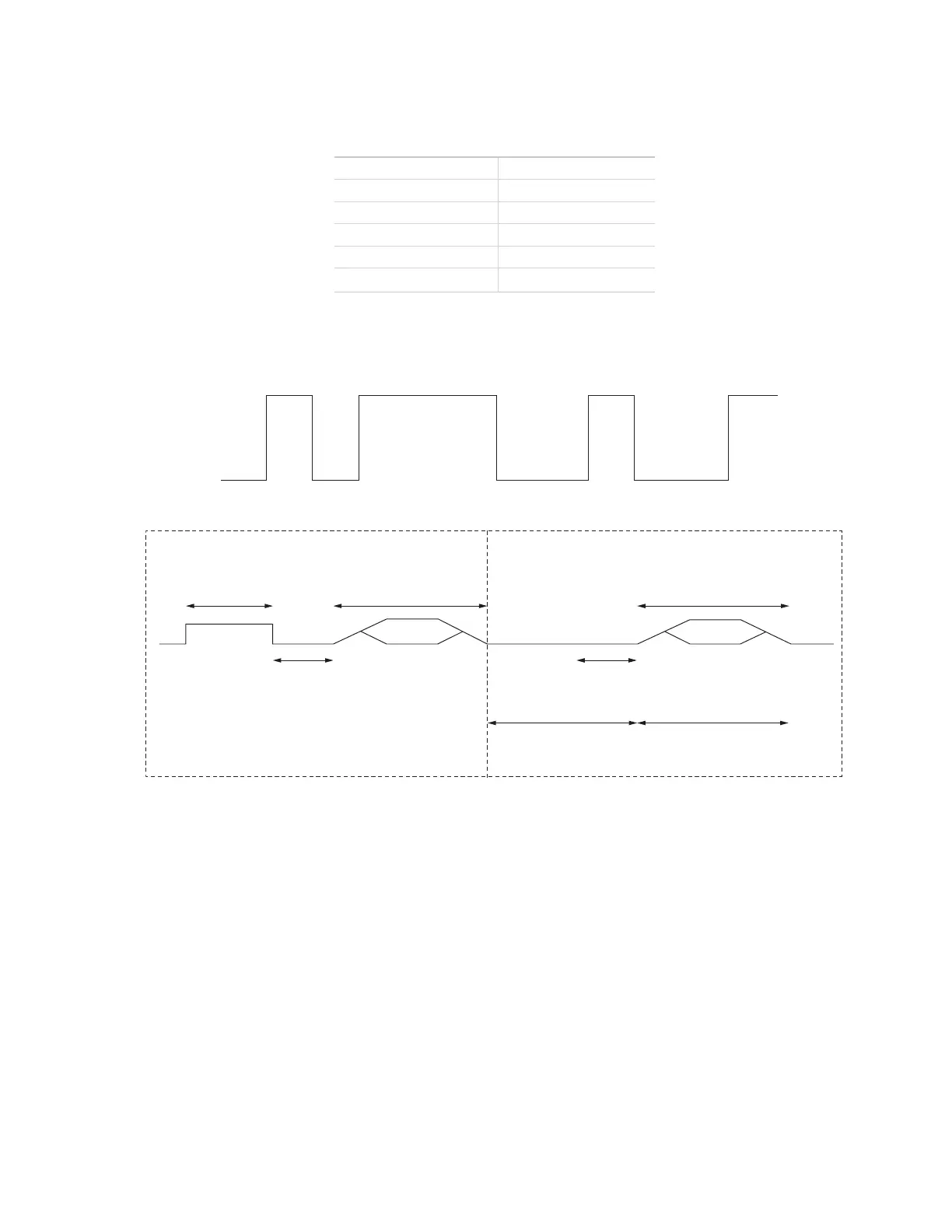
START STOPD0 D1 D2 D3 D4 D5 D6 EP
Figure 4 Example SDI-12 transmission of the character 1 (0x31)
Break
(at least 12 ms)
Marking
(at least 8.33 ms)
Marking
(at least 8.33 ms)
Command Response
SENSORDATA LOGGER
Maximum time*Sensor must respond
within 15 ms
*Maximum time is dependent upon the amount of data returned for the command sent.
Figure 5 Example data logger and sensor communication
COMMON SDI12 COMMANDS
This section includes tables of common SDI-12 commands that are often used in an SDI-12 system and the
corresponding responses from METER sensors.
IDENTIFICATION COMMAND aI!
The Identification command can be used to obtain a variety of detailed information about the connected
sensor. An example of the command and response is shown in Example 1, where the command is in bold and
the response follows the command.