9
DDI SERIAL TIMING
Table8 lists the DDI serial communication configuration.
Table8 DDI serial communication configuration
Baud Rate 1200
Start Bits 1
Data Bits 8 (LSB first)
Parity Bits 0 (none)
Stop Bits 1
Logic Standard (active high)
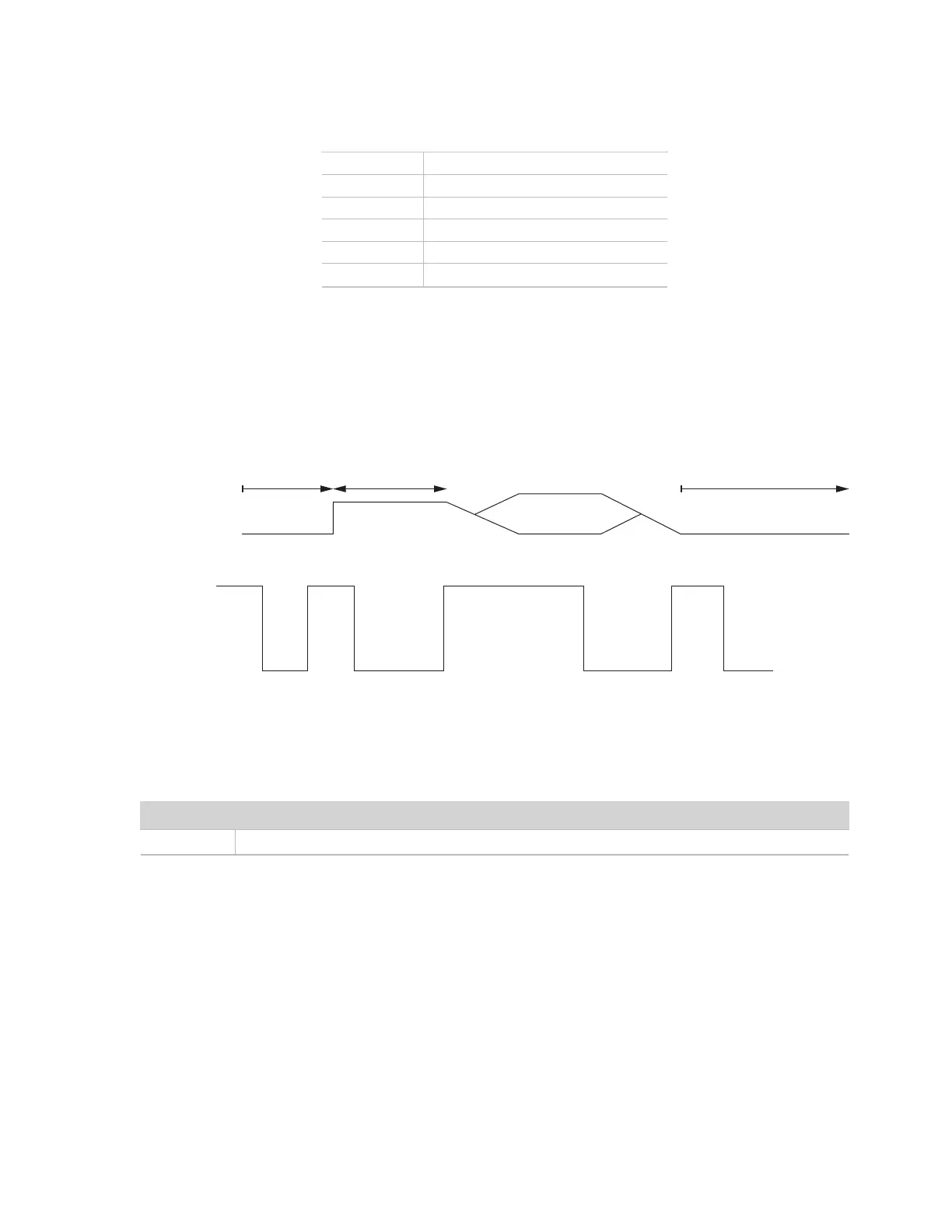
At power up, the sensor will pull the data line high within 100 ms to indicate that the sensor is taking a reading
(Figure 6). When the reading is complete, the sensor begins sending the serial signal out the data line adhering
to the format shown in Figure 7. Once the data is transmitted, the sensor goes into SDI-12 communication
mode. To get another serial signal, the sensor must be power cycled.
NOTE: Sometimes the signaling from the sensor can confuse typical microprocessor UARTs. The sensor holds the data line low while
taking measurements. The sensor raises the line high to signal the logger that it will send a measurement. Then the sensor may take some
additional measurements before starting to clock out the first data byte starting with a typical start bit (low). Once the first start bit is sent,
typical serial timing is valid; however, the signal transitions before this point are not serial signaling and may be misinterpreted by theUART.
SDI-12 ready
DDI serial
duration
Up to 100 ms
Power applied
Figure 6 Data line DDI serial timing
START STOPD0 D1 D2 D3 D4 D5 D6 D7
Figure 7 Example DDI serial transmission of the character 9 (0x39)
DDI SERIAL RESPONSE
This section contains tables detailing the DDI serial response.
Table9 DDI serial response
Command Response
-
<TAB><waterPotential> <temperature><CR><sensorType><Checksum><CRC>
DDI SERIAL CHECKSUM
The legacy checksum is computed from the start of the transmission to the sensor identification character.
These checksums are used in the continuous commands R3 and R4 as well as the DDI serial response.
Legacy checksum example input is <TAB>-34.8 22.3<CR>k and the resulting checksum output is @.