The M2 Quick Start Guide
“Using the Auto optical edge probe” Example
The Auto optical edge probe enters points automatically upon crossing
an edge. The point acquired at the edge crossing will be added to the
current feature measurement routine. The M2 Software supports
measuring features with the “Auto edge probe” using the following
procedure:
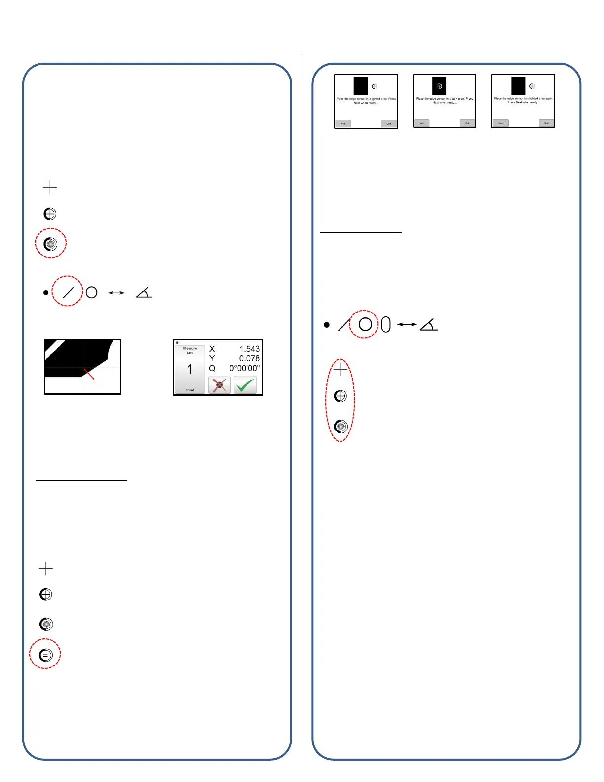
■ Select the Auto optical edge probe from the probe menu.
■ Press a Measure Feature button from the center or bottom toolbar.
■ Cross an edge on the feature to be measured, a point enter sound
will be played and the point will be added to the current measurement.
■ After the desired number of points have been probed, press
“Done”(Green Check Button) to complete the measurement.
Note: If a measurement fails after pressing “Done”, please refer to the
probe points requirements list or the measure feature examples, both
found in Section 2.
Optical Edge Teach
The use of the Manual and Auto Optical Edge probes requires that a
valid optical edge teach routine be performed in the M2 software.
“Teaching Optical Edge” Example
■ Select the “Probe Teach” button located in the probe menu.
■ Follow the on-screen instructions for positioning your optical sensor
throughout the 3-stage teach routine.
■ At the completion of the teach routine a message will be displayed
indicating the results of the teach. After a successful teach, the Optical
Edge probes can be used to perform feature measurements. If an
edge teach failure occurs, attempt the teach routine again. If failure
continues, please contact your machine service provider for
assistance.
Measure Feature:
“Measure Circle” Example
The M2 Software supports measuring Circle features and can be
accomplished using the following procedure:
■ Select the Measure Circle button from the Measure Toolbar.
■ Select a crosshair or optical edge probe from the probe menu.
■ Press “Done” to complete the Circle Measurement. The Circle is
added to the Feature List and Part View.
All supported feature types can be measured explicitly using the
same procedure described above.
Points requirements for probed and constructed
features:
■ Point Features require one (1) or more points. When more than one
(1) point is probed or used in a construction, the average point is the
result.
■ Line Features require two (2) or more points. When more than two
(2) points are probed, a data fit type is applied to the feature’s data
cloud.
■ Circle and Arc Features require three (3) or more points. When
more than three (3) points are probed, a data fit type is applied to the
feature’s data cloud.
■ Angle Features require four (4) or more points. The first (2) points
must be probed on one leg of the angle, followed by two (2) additional
points on the second leg. More points can be added after the initial (4)
in any location of the angle’s legs.
 Loading...