Do you have a question about the Metra Electronics 99-4700 and is the answer not in the manual?
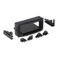
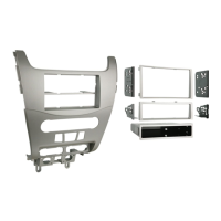
Slide the aftermarket head unit into the kit and secure with shaft nuts.
Cut shaft supports, slide DIN cage into kit, bend tabs, and secure unit.
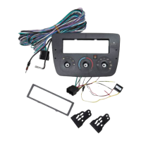
Locate factory harness, use mating adaptor, and tape unused wires.
Reconnect battery, test unit, and mount assembly to sub-dash.
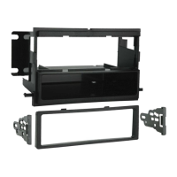
Skip to step 3 for flush and 1/2" extended applications.
Cut slots to 1/4" for 1/2" recessed applications.
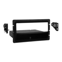
Slide spacers into slots on the Extension Housing for 1" extended.
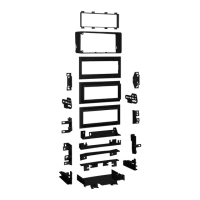
Mount Extension Housing to Radio Housing with carriage bolts and keps nuts.
Mount brackets to housing assembly through side holes with supplied hardware.
| Brand | Metra Electronics |
|---|---|
| Model | 99-4700 |
| Category | Automobile Accessories |
| Language | English |