CHRYSLER CAN BUS INTERFACE
©Copyright 2004-2007 Metra Electronics Corporation
1-800-221-0932
www.metraonline.com
CHTO-01
INSTALLATION INSTRUCTIONS
* IMPORTANT WARNING
THIS PRODUCT INCLUDES INSTRUCTIONS FOR INSTALLATION WHICH MUST
BE CAREFULLY FOLLOWED. THE INSTRUCTIONS ARE WORDED IN SUCH A
MANNER TO ASSUME THAT THE INSTALLER IS CAPABLE OF COMPLETING
THESE TYPE OF ELECTRONIC INSTALLATIONS. IF YOU ARE UNCLEAR AS TO
WHAT YOU ARE INSTRUCTED TO DO OR BELIEVE THAT YOU DO NOT UNDER-
STAND THE INSTRUCTIONS SO AS TO PROPERLY AND SAFELY COMPLETE
THE INSTALLATION YOU SHOULD CONSUL
T A TECHNICIAN WHO DOES HAVE
THIS KNOWLEDGE AND UNDERSTANDING. FAILURE TO FOLLOW THESE
INSTRUCTIONS CAREFULLY AND TO INSTALL THE INTERFACE AS
DESCRIBED COULD CAUSE HARM TO THE VEHICLE OR TO SAFETY
SYSTEMS ON THE VEHICLE. INTERFERENCE WITH CERTAIN SAFETY
SYSTEMS COULD CAUSE HARM TO PERSONS AS WELL. IF YOU HAVE ANY
QUESTIONS IN THIS REGARD PLEASE CALL THE HELP LINE OR THE
METRA AT 1-800-221-0932 FOR ASSISTANCE.
CHTO-01 CHTO-01
* READ IMPORTANT WARNING INSIDE
BEFORE ATTEMPTING ANY INSTALLATION
THE CHTO-01 IS DESIGNED TO BE USED WITH VEHI-
CLES THAT HAVE A FACTORY AMPLIFIED SYSTEM.
THE CHTO-01 WILL PROVIDE A 12VOLT SWITCHED
WIRE FOR PROPER RADIO OPERATION. THE CHTO-01
NOW PROVIDES MUTE, PARKING BRAKE, VSS OR
SPEED SENSE, AND A REVERSE OUTPUT TO MAKE
INSTALLING AN AFTERMARKET NAVIGATIONAL
RADIO SIMPLER AND LESS TIME COMSUMING.
• Cutting Tool • Tape • Crimping Tool • Connectors
TOOLS REQUIRED FOR INSTALLA
TION
AUDIO LEVEL CONTROL
When using the CHTO-01 with a radio that has a high audio pre-out voltage,
usually greater than 2 volts, the audio signal may become distorted.
To resolve this follow these steps:
1. Make sure the ignition is turned to the “off” position.
2. Disconnect both of the harnesses from the CHTO-01.
3. Remove the cove from the CHTO-01 by squeeezing the sides of the
cover to release the clips.
4. Locate the potentiometer on the circit board. See Figure A.
5. Taking a small flat headed screwdriver, turn the potentiometer counter
-
c
lockwise to lower the input level going to the factory amplifier.
6. After making the adjustment, replace the cover and reconnect wire
harnesses.
4
REV. 10-01-07 INSTCHTO-01
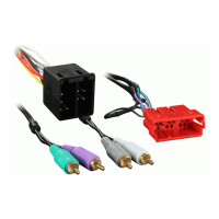
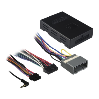
INTERFACE COMPONENTS
• CHTO-01
• 14 PIN HARNESS WITH RCA’S
• 12 PIN HARNESS TO 22 PIN CHRYSLER HARNESS