Chapter II
32 Portable digital multimeter
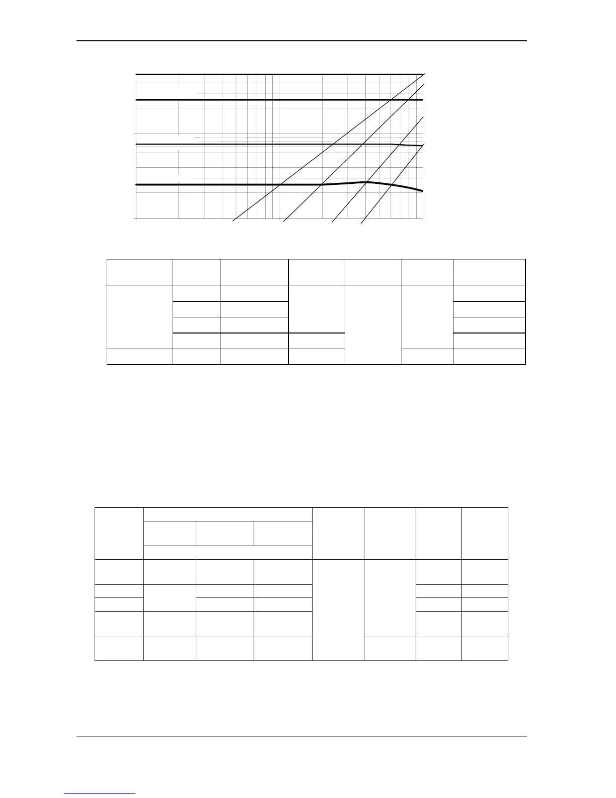
Curve showing typical measurement error (5 V, 50 V, 500 V ranges)
1000 pts
1 kHz
10 kHz
100 kHz
Vin = 100 % F.S.
Vin = 50 % F.S.
Vin = 15 % F.S.
50000 pts
25000 pts
7500 pts
2500 pts
1%
5%
10%
2%
Vin = 5 % F.S.
5.3.
DC current
Selector
switch pos. Ranges Accuracy
Max volt.
drop Protection
Fuses∗
Resolution
500 µA 0.2%R + 5 D 10 nA
5 mA 0.2%R + 2 D 100 nA
50 mA 0.05%R+ 2 D
700 mV
1 µA
µA mA
500 mA 0.2%R + 2 D 1.5 V
F1 + F2
10 µA
10 A∗∗ 10 A 0.5%R + 5 D 500 mV
600 V
RMS
F2 1 mA
∗ refer to fuse specifications, §. 6.1.1.
∗∗ acceptance 20 A overload during 30 s. max, observing a 5 min break at least between two
measurements
Number of counts : 50 000 (or 5 000, refer to §. 3.4)
Range selection : automatic or manual for the 500 µA, 5 mA, 50 mA, 500 mA ranges
Additional error in Pk +/- mode for a pulse width of ≥ 1 ms : 1% R ± 50 D
For measurements performed on alternative signals, the selected range must tally with the max.
value of the signal peak.
5.4. AC currents (AC and AC+DC)
Accuracy
40 Hz to
5 kHz
5 to 10 kHz 10 to 30 kHz
Ranges
5 % to 100 % of range
Protection
Fuses∗
Resol.
Max.
crest
500 µA
0,75 % R
+ 30 D
1,5 % typ. 4 % typ. 10 nA 1 mA
5 mA 1,5 % typ. 4 % typ. 100 nA 10 mA
50 mA
0,6 % R
+ 30 D
1,5 % typ. 4 % typ. 1 µA 100 mA
500 mA
0,7 % R
+ 30 D
1,5 % typ. 4 % typ.
F1 + F2
10 µA 1 A
10 A∗∗
1%R+30D
Æ 2 kHz
1,5 % typ. ////////////
600 V
RMS
F2 1 mA 30 A
∗ refer to fuse specifications, §. 6.1.1.
∗∗ acceptance 20 A overload during 30 s. max, observing a 5 min break at least between 2
measurements