EasyManua.ls Logo

Metrix ST5484E - User Manual

Metrix ST5484E
7 pages
Print Icon
To Next Page IconTo Next Page
Loading...
Manual
ST5484E 2-Wire Seismic Vibration Transmitter
Document 9162
Rev. T (Oct 2013)
1. Overview
The Model ST5484E Seismic Vibration Transmitter combines a vibration sensor and signal
conditioner in a single package for sensing machinery vibration level and transmitting a
proportional 4-20 mA signal directly to a PLC, DCS, monitor, or computer. The 2-wire flying lead
version is shown at right. Versions with 4 wires, terminal blocks, or MIL-type connector are also
available.
The transmitter has no moving parts and is encapsulated in a stainless steel housing. Each
transmitter is factory calibrated to the sensitivity marked on the label. An optional dynamic
signal output can be specified.
2. Mounting
It is important the transmitter body be solidly mounted to the machine surface. Refer to section 6 on transducer placement.
Different machine preparations are required for the two basic transmitter mounting styles; NPT (National Pipe Thread) and
machine thread (UNF and Metric). Transmitters with the NPT type mounting stud are secured by the thread engagement and
the base of the transmitter does not come in contact with the machine surface. On the other hand, transmitters with the
machine thread studs must make contact with the machine surface. The base of the transmitter must make square and
direct contact. This requires preparing the surface of the machine with a 1 1/2 inch counter bore (surfacing tool). This tool
can be used with a portable drill equipped with a magnetic base but care must be taken so that the tapped and threaded hole
is perpendicular to the machined surface. The transmitter must make contact all the way around its base surface. Contact
Metrix for more detailed instructions for using a counter bore.
If installing a transmitter with a standard 1/4 inch NPT stud, drill a hole using a 7/16 inch bit, 5/8-7/8 inch deep. Then tap
using a 1/4 - 18 NPT (tapered pipe tap). Hand tighten the transmitter and then turn an additional 1 to 2 turns using a wrench
on the wrench flats. Do not use a pipe wrench. A pipe wrench can apply extreme forces to the body and potentially damage
electronic components. A minimum of five (5) threads of engagement should be made. A 1/4 inch to 1/2 inch NPT bushing is
available for mounting the transmitter in existing 1/2 inch NPT holes. Also, a Model 7084 Flange Adapter can be used
between the transmitter and the machine surface when there is not enough surface thickness to drill and tap a hole. The
flange adaptor mounts with three small screws.
If installing a transmitter with one of the straight machined thread sizes, follow standard drill and tap procedures. Be sure to
not drill a hole larger that the counter bore pilot diameter before using the counter bore to prepare the machine surface.
Drill out the hole with the correct tap drill size after preparing the surface.
The sensitive axis of the transmitter is in line with the mounting stud. The transmitter can be oriented in any (0 to 360
degree) position.

Other manuals for Metrix ST5484E

Question and Answer IconNeed help?

Do you have a question about the Metrix ST5484E and is the answer not in the manual?

Summary

Overview

Mounting

Wiring

General Wiring

Connect field wiring per diagrams for single/multiple transmitter loops.

Intrinsically Safe Installation

Wiring for hazardous locations (CSA, IECEX, ATEX) with barrier voltage/resistance limits.

Explosion-Proof Installation (CSA)

CSA explosion-proof installation for Class I/II hazardous locations.

Flame-Proof Installation (ATEX, IECEX)

ATEX/IECEx flame-proof installation for hazardous locations, including conditions.

Electromagnetic Compatibility

Connection to PLC or Indicating Instrument

Typical Transmitter Placement

Calibration

Zero Verification

Verify 4 mA output in absence of vibration using a vibration-free surface.

Span Verification

Verify 20 mA output by subjecting transmitter to known full-scale vibration.

Optional Dynamic Output

Specifications and Ordering

Overview

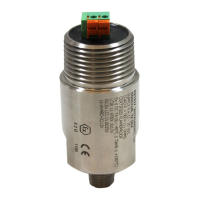
The ST5484E is a 2-wire seismic vibration transmitter designed to monitor machinery vibration levels and transmit a proportional 4-20 mA signal to a PLC, DCS, monitor, or computer. It integrates a vibration sensor and signal conditioner into a single, encapsulated stainless steel package. The device is available in various configurations, including a 2-wire flying lead version (shown in the overview), as well as versions with 4 wires, terminal blocks, or MIL-type connectors. Each transmitter is factory calibrated to a specific sensitivity, which is marked on its label. An optional dynamic signal output can also be specified.

Function Description:

The ST5484E measures seismic vibration, specifically vibration velocity, at the machine's attachment point. It outputs a 4-20 mA current signal that is proportional to the vibration level, using engineering units of inches per second (in/s) or millimeters per second (mm/s), depending on the selected ordering option. The transmitter's sensitive direction is along the long axis of its cylindrical body, meaning it does not measure side-to-side motion. The device utilizes a true RMS amplitude detection circuit. For units supplied with a full-scale range in peak units, the underlying RMS measurement is scaled by a factor of 1.414 to provide a "derived peak" rather than a true peak measurement.

Important Technical Specifications:

  • Power Requirements:
    • Minimum operating voltage at the transmitter: 11 VDC.
    • Minimum loop power supply voltage: 11 VDC plus 1 volt for each 50 ohms of total loop resistance.
    • Maximum loop power supply voltage: 30 VDC.
    • Maximum loop resistance (R_L) for a 24 VDC loop supply: 650 ohms.
  • Output Signal:
    • Vibration level at 0.0 in/s (no vibration): 4.0 mA (± 0.1 mA).
    • Vibration level at 1.0 in/s (full scale vibration): 20.0 mA (± 0.5 mA).
  • Optional Dynamic Output:
    • Acceleration signal with a sensitivity of 100 mV/g.
    • Filtered to the same frequency band as the 4-20mA velocity measurement.
  • Hazardous Location Approvals:
    • Intrinsically Safe (CSA, IECEx/ATEX): Requires specific wiring per Metrix drawings (9426 for CSA, 9278 for IECEx/ATEX). Leads must be terminated in an enclosure with at least IP20 protection. Ambient temperature range: -40°C to 100°C. Minimum supply voltage for intrinsically safe installations is 19.1 VDC plus 1 volt for each 50 ohms of loop resistance. Maximum loop power supply voltage to safety barrier: 26 VDC. Maximum loop resistance with 26 VDC supply: 345 ohms.
    • Explosion-Proof (CSA): Certified Class I (B, C & D); Class II (E, F & G). Requires certified explosion-proof conduit and junction boxes.
    • Flame-Proof (ATEX, IECEx): Certified Ex d IIC T4 Gb. Requires certified flame-proof conduit and junction boxes. The 8200-001-IEC elbow is required for this approval. ATEX Conditions for Safe Use: Uo ≤ 30V, Io ≤ 100mA, Po ≤ 0.75W. Ambient Operating Temperature: -40°C to +100°C.
  • Electromagnetic Compatibility (EMC):
    • Field wiring must be shielded twisted pair cable enclosed in grounded metallic conduit, or double shielded twisted pair cable with a metallic body cable gland fitting and outer shield grounded.
    • Metrix ferrite bead kit (p/n 100458) is recommended as an extra precaution.

Usage Features:

  • Mounting:
    • Solid mounting to the machine surface is critical.
    • NPT Type Mounting: Secured by thread engagement; base does not contact machine surface. For 1/4 inch NPT stud, drill a 7/16 inch hole, 5/8-7/8 inch deep, then tap with 1/4 - 18 NPT. Hand tighten, then turn 1-2 additional turns with a wrench. Do not use a pipe wrench. Minimum of five threads of engagement. A 1/4 inch to 1/2 inch NPT bushing is available for existing 1/2 inch NPT holes.
    • Machine Thread Studs (UNF and Metric): Base must make square and direct contact with the machine surface. Requires preparing the surface with a 1 1/2 inch counter bore. Ensure the tapped hole is perpendicular to the machined surface.
    • Flange Adapter: Model 7084 Flange Adapter can be used when surface thickness is insufficient for drilling and tapping.
    • Orientation: The sensitive axis is in line with the mounting stud; the transmitter can be oriented in any (0 to 360 degree) position.
    • Typical Placement: Horizontal mounting at bearing housings is common, as machines are often more compliant in the horizontal axis.
  • Wiring:
    • Connected like other loop-powered transmitters.
    • Single- and multiple-transmitter loops are supported.
    • Conduit Attachment: Avoid unsupported conduit lengths and excessive mass. Use a "Y" type conduit elbow (e.g., Metrix 8200) to prevent the conduit from extending too far. Use a small length of flexible conduit to mechanically isolate the transmitter from rigid conduit vibrations.
  • Connection to PLC/DCS:
    • The ST5484E requires loop power, which may be provided by the PLC/DCS analog input channels or an external power supply.
    • Alarm Configuration: Program a time delay (e.g., 2-3 seconds) into alarms to prevent nuisance alarms from momentary "jolts" during start-up or operating condition changes. A start-up lockout (longer time delay) may also be needed for rough starting machinery.
  • Optional Dynamic Output Usage:
    • Only use an electrically-isolated or battery-powered portable vibration analyzer.
    • Turn off instrument sensor power when connecting a portable analyzer or data collector.
    • Be aware that low input impedance analyzers can cause 20-30% signal attenuation.
    • This signal is for temporary connection only; permanent connection may violate hazardous location requirements.
    • Avoid introducing electrical noise or mechanical vibrations when connecting.
    • Ensure leads do not touch conduit or each other when not in use, as this affects the 4-20 mA output.
    • Do not use leads longer than 5m (16 feet) to avoid electrical noise and high-frequency signal attenuation.

Maintenance Features:

  • Calibration Verification:
    • The transmitter is factory calibrated; no Zero or Span adjustments are available on the unit.
    • Zero Verification: In the absence of vibration, the output current should be 4 mA ±0.1 mA. If ambient vibration exceeds 2% of full scale, remove the transmitter and place it on a vibration-free surface (e.g., foam) for measurement.
    • Span Verification: Subject the transmitter to a known vibration within the full-scale range marked on the label. If tested at full scale with a portable vibration shaker, the output should be 20 mA ±0.5 mA.

Metrix ST5484E Specifications

General IconGeneral
BrandMetrix
ModelST5484E
CategoryTransmitter
LanguageEnglish