Doc# M9162• REV AB (April 2019) Page 3 of 12
Example:
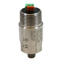
Component Resistance
Signal wiring 10 W
DC Input Impedance of receiver 250 W
TOTAL LOOP RESISTANCE 260 W
Minimum supply voltage = 260 W (1 V/50 W) + 11 V = 16.2 VDC
The maximum loop power supply voltage that may be applied is 29.6 VDC (intrinsically safe)
or 30VDC (explosion proof and non-incendive). The maximum loop resistance (RL) is calcu-
lated by the equaon: RL = 50 (VS - 11) W
Example: RL = 50 (24 - 11) = 650 W for a 24 VDC loop supply.
3.2 Intrinsically Safe Installaon In Hazardous Locaons
Connect the eld wiring in accordance with Metrix drawing 9426 for CSA Class I, (A,B,C &
D) and Metrix drawing 9278 for IECEx / ATEX (Ex ia IIC T4 Ga) approvals. The leads must be
terminated inside an enclosure with a degree of protecon of at least IP20. A Metrix elbow
from the 8200 series may be used for these purposes. Refer to Metrix Datasheet 1004457
for addional details on accessories. The ambient temperature range is -40°C to 100°C.
The transmier requires a minimum of 11 VDC for proper operaon. The voltage drop
across the specied non-isolated barriers with a 20 mA loop current is 8.1 VDC. As such, The
minimum loop power supply voltage required is 19.1 VDC plus 1 volt for each 50 W of loop
resistance. The maximum loop power supply voltage that may be applied to the safety bar-
rier is 26 VDC. Therefore, the maximum loop resistance with a 26 VDC supply is 345 W.
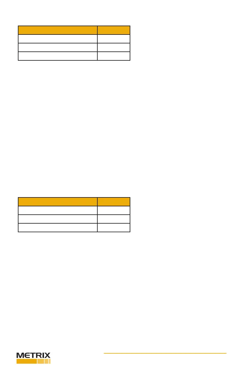
Example:
Component Resistance
Signal wiring 5 W
DC Input Impedance of receiver 100 W
TOTAL LOOP RESISTANCE 105 W
Minimum supply voltage = 105 (1 V/50 W) + 19.1 V = 21.2 VDC
3.3 Explosion-Proof Installaon In Hazardous Locaons (CSA)
Some models of ST5484E transmiers are CSA cered explosion-proof, CSA US/C, Class I,
Div 1, Grps B-D and Class II, Div 1, Grps E-G (explosion proof). Connect the eld wiring in ac-
cordance with the appropriate poron of Figure 1. Refer to secon 3.1 for loop voltage and
resistance requirements. All conduit and juncon boxes used must be cered explosion-
proof for the class, division, and group required by the applicaon. Installaon of the trans-
mier must meet all of the explosion-proof installaon requirements of the local governing
agency and facility safety procedures.
3.4 Flame-Proof Installaon In Hazardous Locaons (ATEX, IECEX)
Some models of ST5484E transmiers are ATEX/IECEx cered ame-proof, Ex d IIC T4 Gb. Con-
nect the eld wiring in accordance with the appropriate poron of Figure 1. Refer to secon
3.1 for loop voltage and resistance requirements. All conduit and juncon boxes used must be
cered ame-proof for the area required by the applicaon. Installaon of the transmier
must meet all of the ame-proof requirements of the local governing agency and facility safety
procedures. The Metrix part 8200-001-IEC elbow is required to meet this approval.
 Loading...