Doc# M9162• REV AB (April 2019) Page 7 of 12
5. CONNECTION TO PLC OR OTHER INDICATING INSTRUMENT
The rst step in conguring the PLC, DCS, or other recording instrument is to determine the source
of power. The ST5484E requires loop power. Some analog input channels on a PLC or DCS, for
example, provide this power from within. If they do not provide power, an external power supply
must be provided. Connect the transmier eld wiring using standard instrumentaon pracces.
Scaling of the display is on the basis of the range of the transmier. The measurement parameter
name is “vibraon” and the units are “in/s” (inches per second) or “mm/s” (millimeters per sec-
ond). The example below is based on a standard 1.0 in/s transmier.
6. TYPICAL TRANSMITTER PLACEMENT
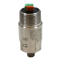
The ST5484E measures seismic vibraon (i.e., vibraon velocity) at the aachment point on the
machine, using engineering units of in/s (inches per second) or mm/s (millimeters per second)
depending on the selected ordering opon. The transmier’s sensive direcon is through the long
axis of its cylindrical body. It will not measure side-to-side moon.
Typical transmier mounng for casing vibraon measure-
ments is in the horizontal direcon at the bearing housings
as depicted in Figure 2. The horizontal direcon usually
incurs more vibraon because most machines’ foundaon
constrains vercal vibraon more than horizontal vibraon.
A horizontal mounng arrangement is also depicted in Figure
3, but with addional detail showing typical accessories.
When ying leads are ordered, a 24- or 72-inch length may
be specied using ordering opon D on the Metrix product
datasheet 1004457. These leads may be cut to length and
then spliced to eld wiring as shown in Figure 3.
Figure 2
Typical transmier
mounng
When vibraon level
at transmier is…
Transmier output
will be…
PLC (or other) should read…
0.0 in/s (i.e. no vibraon) 4.0 mA (± 0.1 mA) 0.00 in/sec
1.0 in/s (i.e. full scale vibraon) 20.0 mA (± 0.5 mA) 1.00 in/sec
Momentary “jolts” that can occur at start-up, or during some operang condion changes, do not
reect a machine’s steady-state operang condion. To prevent such occurrences from generang
nuisance alarms, program a me delay into the alarm such that the indicated vibraon level must
persist above the alarm setpoint for a preset period of me before an alarm is generated. The
indicated vibraon level must cross the threshold level and stay above it for a preset me before
any alarm acon is taken. A 2- to 3-second delay is normally applied to most machinery. Consult
Metrix if you have a queson about your machine’s operang characteriscs.
Some rough starng machinery may also need a start-up me lockout for alarms. A start-up
lockout is dierent than a me delay. A start-up lockout funcons the same as a me delay, but is
usually set to a much longer me. Both may be needed.

 Loading...