Doc# M9162• REV AB (April 2019) Page 8 of 12
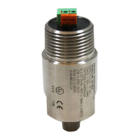
Figure 3
When aaching conduit to the transmier, observe the following:
• Because the transmier is sensive to vibraon, avoid unsupported lengths of conduit and
excessive mass (such as large hubs or juncons) hanging directly o the end of the transmier.
These can introduce unwanted vibraons that do not reect actual machinery vibraon and
cause mechanical stresses that can lead to premature transducer failure.
• A “Y” type conduit elbow, such as the Metrix 8200 series, is preferred because it prevents the
conduit from extending too far away from the transmier, thus liming the likelihood of break-
age. It also precludes long unsupported lengths of conduit directly aligned with the transmit-
ter’s bore (longitudinal axis) as noted in the bullet above.
• Avoid aachment of rigid conduit directly to the transmier; instead, use a small length of
exible conduit to mechanically isolate the transmier from vibraon that might occur in rigid
conduit.
• If a 1-inch to 3/4-inch reducer is used at the elbow, a smaller diameter exible conduit can be
used.
NOTE: Hazardous area locaons do not allow a splice at the locaon shown
in Figure 3. Instead, the splice must be made in a second conduit hub
(meeng splicing requirements) located at the end of exible conduit.
 Loading...