Doc# M9162• REV AB (April 2019) Page 9 of 12
7. INSTALLATION BEST PRACTICES FOR RFI IMMUNITY
The ST5484E is case isolated from the loop power connecon to the
PLC, DCS, SCADA, or other +24 VDC alarm system. With the correct
grounding scheme, this type of isolaon avoids ground loops and re-
sults in good RF immunity. However, in situaons which involve inter-
ference from high-powered transmiers and especially spread-spec-
trum type radios, the ST5484E may become vulnerable to RF noise.
Since it is oen dicult to idenfy these situaons in advance, Metrix
strongly recommends ulizing the following Best Pracces when install-
ing all ST5484E transmiers in the eld:
1. Twist the sensor leads together (at least 10 twists per foot).
2. Slide the twisted leads through the included ferrite core and posi-
on as close to the sensor as praccal. Refer to Figures 4 and 5.
3. If possible, cut the leads short and use a shielded twisted pair. Fol-
low step 2 in this applicaon as well.
As shown in Figure 5, “chokes” that aenuate dierent frequencies can
be created by looping a dierent number of turns through the ferrite
core. More wire turns adds more inductance, aenuang progressively
lower frequencies. Mulple “chokes” can be created in this manner
and placed in series on the wire leads to cover a broad frequency band.
Always locate the choke covering the higher frequency band closest to
the sensor.
8. CALIBRATION
The ST5484E transmier has been factory calibrated for the full-scale vibraon level marked
on the label. If the calibraon is in doubt, the unit can be veried in the eld by following
the procedures outlined below. Note that there are no Zero and Span adjustments on the
transmier. Addionally, the transmier uses a true RMS amplitude detecon circuit; units
supplied with a full scale range in peak units scale the underlying RMS measurement by a
Figure 5: Leads may also be
looped through the ferrite
core to aenuate dierent
frequencies. The opmal
number of loops will vary
by applicaon and the
interfering frequency(ies).
Figure 4: Leads may be
simply fed straight through
the ferrite core.
factor of 1.414 to provide a “derived peak” rather than true peak measurement.
7.1 Zero Vericaon
In the absence of vibraon the output current should be 4 mA ± 0.1 mA. If the ambient
vibraon exceeds 2% of full scale, the transmier should be removed from the machine and
placed on a vibraon free surface for this measurement. Oen a piece of foam can be used
to isolate the transmier from external moon.
7.2 Span Vericaon
Subject the transmier to a known vibraon within the full scale range marked on the label.
If you are using a portable vibraon shaker where it can be tested at full scale, the output
should be 20 mA ± 0.5 mA.
9. OPTIONAL DYNAMIC OUTPUT
The transmier can be ordered with an oponal dynamic output. Transmiers supplied with
this opon can be idened by the presence of four ying leads instead of two (Figure 6), or
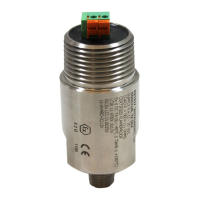
four terminal connecons instead of two (Figure 7).
The dynamic output is an acceleraon signal with a sensivity of 100 mV/g, ltered to the

 Loading...