14
SERVICE and REPLACEMENT PARTS (continued)
Warning: Only factory approved service agents should attempt
to service, repair or replace electrical components,
wiring or power cord.
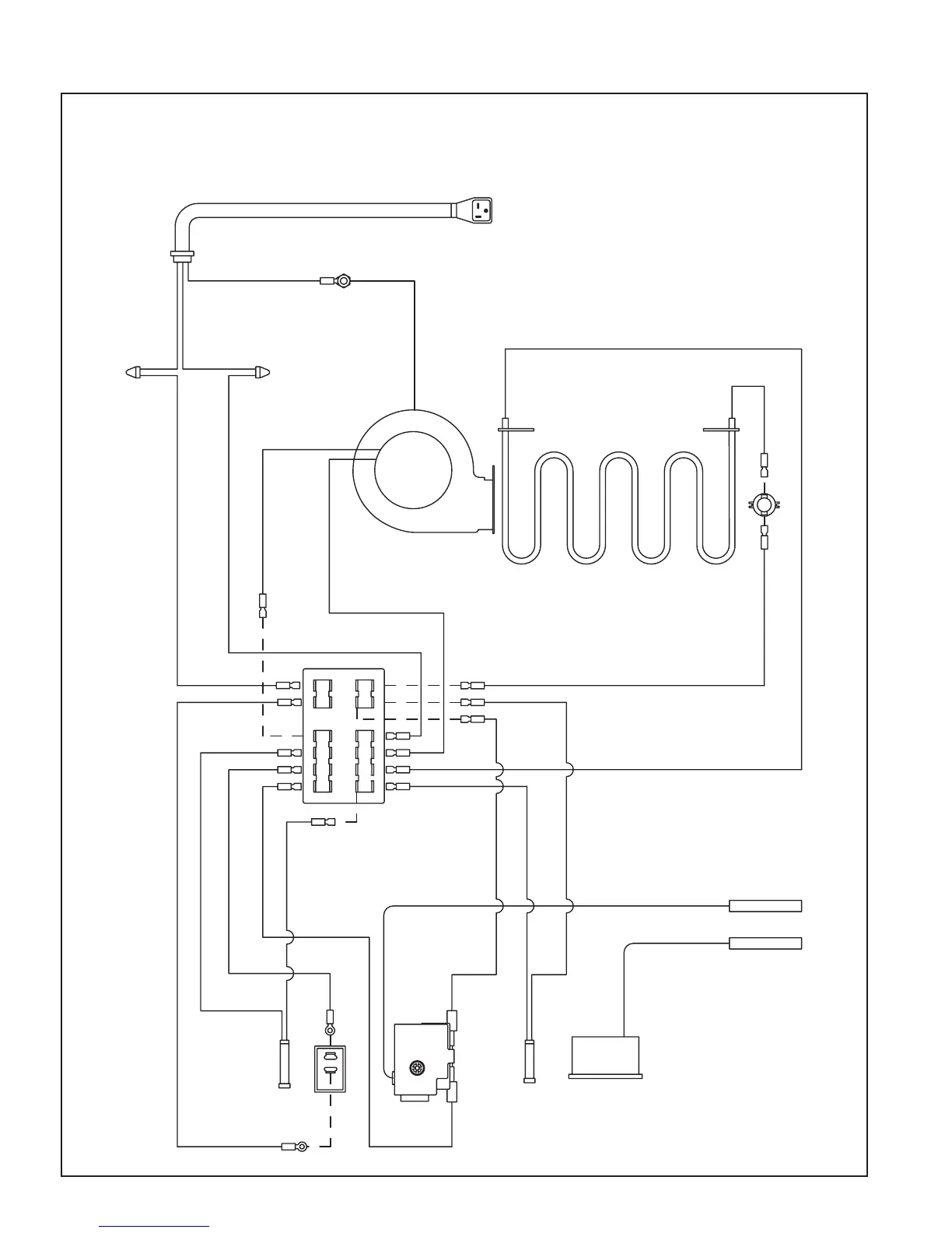
Wiring Diagram
12
RED LIGHT
22
BLACK X 23"
BLACK X 15"- SPADE TO RING
BLACK X 15" -SPADE TO RING
MASTER SWITCH
23
BLACK X 30"
WHITE X 30"
BLACK X 30"
BLACK X 30"
7
WIRE NUT
WIRE NUT
WHITE X 18"
BLACK X 15"
WHITE
BLACK
BLOWER
THERMAL CUT OUT
AIR HEAT ELEMENT
19
9
22
10
11
20
21
9
611
24
22
19
10
23
17
22
16
21
15
24
18
20
14
19
13
11 10 912 87
543621
A
A
7
8
2
24
8
2
6
RED LIGHT
THERMOMETER BULB
THERMOSTAT BULB
HEAT
THERMOSTAT
BLACK X 15"
STRAIN RELIEF
GROUND
GREEN
20A RIGHT ANGLE
PLUG POWER CORD
SHOWN
BLACK X 15"
23
20
ON
OFF
GREEN WIRE
 Loading...