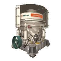
Do you have a question about the Metso HP3 and is the answer not in the manual?
The main frame liner and arm guards are installed at the beginning of the assembly process.
Importance of checking Main Frame Liners at every liner change to prevent costly damage.
Main Frame seat liners protect the main frame seating surface from damage caused by ring movement.
Procedure for measuring the distance between the adjustment ring and main frame to detect wear.
The ring assembly consists of the adjustment ring with hydraulic motor and the clamping ring with its system.
Procedure for installing the clamping ring assembly, covering cleaning, valve engagement, and component placement.
Procedure for cylinder installation, including measuring rod pull-out distance based on crusher size.
Procedure for setting end float by ensuring the pinion is tight against the bushing flange and using a feeler gauge.
Procedure for installing the eccentric bushing, emphasizing precise alignment of oil holes.
Steps for the break-in procedure after bushing installation, covering lubrication temperature, run-in time, and load.
Procedure for socket removal, requiring heating the circumference to 145°F (80°C).
Steps for socket installation, including centering bolts, heating, sliding, and fixation with torque check.
Instructions for cooling head ball in dry ice and re-installing the safety bolt with Loctite 277.
Contact must be on the thin helix portion; wedge bolt stays vertical; spring washers prevent flattening.
Controls minimum lubrication pressure at 0.8 bars; acts as a critical safety device.
Measures tramp release circuit pressure, converting it to a 4-20mA signal for automation.
Counts pignon teeth turns for setting relation, connected to lubrication unit or PLC.
Two sensors measure thrust bearing and oil return line temperatures, outputting 4-20mA signals.
| Brand | Metso |
|---|---|
| Model | HP3 |
| Category | Industrial Equipment |
| Language | English |


