8 7 LCP9H 70 en Liwa
4.1 Functionality
The functionality of the LCP9H push buttons and purpose
of the LEDs are described below in 4.1.1-7.
Functionality of the LCP9H is lost in the following cases:
If the supply power (external 24 VDC or loop pow-
ered from VG) is disconnected.
If there is no communication between the LCP9H
and the VG9000H, e.g. the cable is broken or discon-
nected.
If the polarity of wires is incorrect.
If the Loop A (7, 8) and Loop B (9, 10) wires are mixed
in the VG9000H.
These above-mentioned cases do not affect the valve posi-
tion. Alarm LED is blinking in those cases.
The buttons need to be pushed (0.2–10 seconds) and
released to perform the desired function.
4.1.1 Close button
This functionality is only available in LCP9H and
LCP9HE. LCP9HW and LCP9HEW do not have the
valve closing functionality.
The purpose of the Close button is to manually close
or open the valve depending on the assembly and
configuration of the valve. It means that this will
drive the valve to safety position.
4.1.2 Open button
The purpose of the Open push button is to return
the valve to the normal operating position after the
emergency trip.
The Open button is operational only when the mA
signal from the safety system to VG9000H is in 12.0-
15.0 mA.
The Ready-to-Open LED is lit when mA signal from
the safety system is 12.0 - 15.0 mA. The Open button
is then operational.
Push and release the Reset button to return the valve
to the normal operating position.
4.1.3 PST button
The purpose of the PST button is to start the partial
stroke test (PST) manually or to cancel the manual
partial stroke test of the emergency isolation valve.
The stroke size of the test can be set via HART (DTM,
EDD) or from the LUI (Local User Interface) of the
VG9000H. See VG9000H manual 7VG970en for details.
The manual test via LCP9H uses the same stroke size
than manual PST programmed into VG9000H itself.
To start the PST test, press and release the PST button
and the PST LED will be illuminated.
To stop the ongoing manual PST test, press and
release the PST button and the manual PST test will be
cancelled. The valve will return to its normal operating
position.
It is also possible to cancel the manual PST test with
this PST button even if the test is started via HART or
LUI.
4.1.4 Ready-To-Open LED
The Ready-To-Open LED is turned on when mA sig-
nal from the safety system to the VG9000H is 12.0-
15.0 mA and the Open button has not yet been
pushed. It indicates that the Open button can be
used.
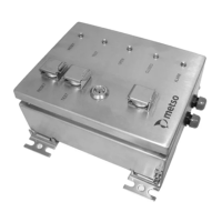
Fig. 9 LCP9HE and LCP9HEL front panel
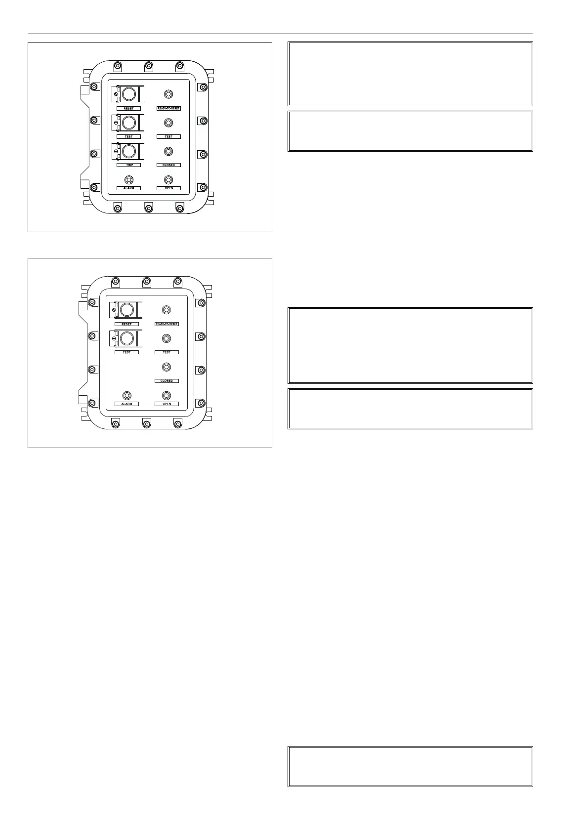
Fig. 10 LCP9HEW and LCP9HEWL front panel
NOTE:
When the button is pushed and released, the valve will be
driven to the safety position; i.e. it will close the valve if it is
the emergency shutdown valve and it will open the valve
when it is the emergency blowdown (venting) valve.
NOTE:
When LCP is used with VG9PST version the trip-functiona-
lity needs to be enabled in VG. It is disabled as default.
NOTE:
When the button is pushed and released, the valve will be
driven to the normal operating position; i.e. it will open the
valve if it is the emergency shutdown valve and it will close
the valve when it is the emergency blowdown (venting)
valve.
NOTE:
Make sure to push the Reset button only when it is safe to
return the valve to the normal operating position.
NOTE:
Make sure to push the Ready-To-Open button only when it
is safe to return the valve to the normal operating position.
 Loading...