CHAPTER 4: QUICKFLY RIGGING
28
should be used to calculate optimum splay angles for
loudspeakers and to predict coverage patterns for
arrays.
NOTE: For more information on GuideALink
configurations, refer to the MG-LEOPARD/900
Assembly Guide (PN 05.243.080.01) available at
www.meyersound.com
.
LEOPARD Splay Angles for Top Flown
Cabinets
When flying LEOPARDs below the 900-LFC, MG-
LEOPARD/900 grid, or MTF-LYON/LEOPARD transition
frame, splay angles of –4.5 to +10 degrees are possible for
the top cabinet with the GuideALink configurations listed in
Table 5.
NOTE: When flying LEOPARDs from the
MG-LEOPARD/900 grid, a splay angle of
0 degrees is recommended for the top cabinet (rear
GuideALinks set to 5, front GuideALinks set to 0) to
ensure that the cabinet aligns with any lasers or incli-
nometers mounted on the grid. To add tilt to the top
cabinet, the actual grid should instead be tilted with
motors attached to the front and rear of the grid. If
just one motor is available, you can attach it to one of
the 13 center pickup points offset from the center of
the grid to achieve the desired tilt.
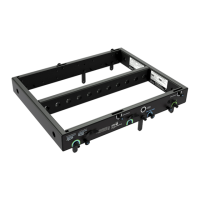
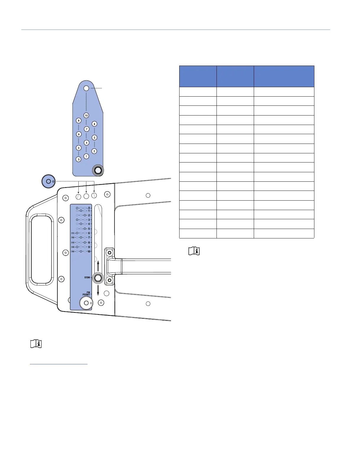
Figure 19: LEOPARD Rear GuideALinks Label
Table 5: LEOPARD (Top Cabinet) GuideALink Configurations
Rear
GuideALinks
Set To
Front
GuideALinks
Set To
Resulting Angle
of Attachment
.5° 0° –4.5°
1° 0° –4°
2° 0° –3°
3° 0° –2°
4° 0° –1°
5° 0° 0°
6° 0° 1°
7° 0° 2°
8° 0° 3°
9° 0° 4°
10° 0° 5°
6° +5° 6°
7° +5° 7°
8° +5° 8°
9° +5° 9°
10° +5° 10°