Do you have a question about the Meyer Sound M1D and is the answer not in the manual?
Crucial safety guidelines for rigging systems and advisories on government regulations.
Defines manual's assumptions on user knowledge and scope regarding rigging systems.
Details load ratings, specifications, and the importance of checking for updates.
Discusses compliance with national, state, and local regulations for sound system suspension.
Clarifies responsibilities for suspension systems and attachment points in rigging.
Outlines regular inspection and maintenance schedules for system integrity and safety.
Emphasizes using approved Meyer Sound parts and policy on non-approved replacements.
Stresses the necessity of trained personnel for the safe assembly and use of QuickFly systems.
Summarizes the main components: MG-1D grid, MTG-1D grid, and MUB-1D U-bracket.
Explains the function, use, and tilt angle capabilities of M1D grid cams.
Provides detailed dimensions and weight specifications for the MG-1D multipurpose grid.
Details the forward flown orientation of the MG-1D grid for M1D/M1D-Sub arrays.
Explains reversed flown orientation for severe upward tilt of the MG-1D grid.
Describes ground stacking an upward tilted M1D/M1D-Sub array using the MG-1D grid.
Details ground stacking a down/forward tilted M1D/M1D-Sub array using the MG-1D grid.
Explains using the MG-1D grid to transition from M2D to M1D arrays.
Details transitioning from M2D to 3 UPA-2P loudspeakers with the MG-1D grid.
Describes transitioning from M2D to a single UPA-1P loudspeaker with the MG-1D grid.
Explains transitioning from M2D to 2 MSL-4 loudspeakers with the MG-1D grid.
Details using the MG-1D grid as a primary frame for flying M2D/M2D-Sub arrays.
Provides detailed dimensions and weight specifications for the MTG-1D top grid.
Describes the forward flown orientation of the MTG-1D grid for M1D/M1D-Sub arrays.
Explains reversed flown orientation for severe upward tilt of the MTG-1D grid.
Provides detailed dimensions and weight specifications for the MUB-1D multipurpose U-bracket.
Details how to set various tilt angles using the MUB-1D U-bracket's mounting holes.
Specifies the load ratings for different mounting holes on the MUB-1D U-bracket.
Describes mounting the MUB-1D U-bracket for floor or ceiling applications.
Explains the flown configuration for the MUB-1D U-bracket with M1D arrays.
| operating frequency range | 32 Hz - 180 Hz |
|---|---|
| frequency response | 35 Hz - 160 Hz ±4 dB |
| phase response | 50 Hz - 120 Hz ±45° |
| maximum peak SPL | 130 dB |
| dynamic range | >110 dB |
| horizontal coverage | 360° |
|---|---|
| vertical coverage | Varies, depending on array length and configuration |
| low frequency transducer | Two 10" cone drivers with neodymium magnets |
|---|---|
| nominal impedance | 4 Ω |
| voice coil size | 2" |
| power-handling capability | 400 W (AES) |
| input type | Differential, electronically balanced |
|---|---|
| maximum common mode range | ±15 V DC |
| input impedance | 10 kΩ differential between pins 2 and 3 |
| amplifier type | Two-channel complementary MOSFET output stages (class AB/bridged) |
|---|---|
| output power | 450 W total |
| THD, IM, TIM | <.02 % |
| load capacity | 4 Ω each channel |
| safety agency rated operating range | 100 - 240 V AC; 50/60 Hz |
|---|---|
| idle current | 0.41 A rms (115 V AC); 0.33 A rms (230 V AC); 0.42 A rms (100 V AC) |
| max long-term continuous current (>10 sec) | 3.2 A rms (115 V AC); 1.6 A rms (230 V AC); 3.7 A rms (100 V AC) |
| burst current (<1 sec) | 5.0 A rms (115 V AC); 2.5 A rms (230 V AC); 5.8 A rms (100 V AC) |
| ultimate short-term peak current draw | 17 A pk (115 V AC); 8.5 A pk (230 V AC); 20 A pk (100 V AC) |
| inrush current | 15 A pk (115 V AC); 13 A pk (230 V AC); 15 A pk (100 V AC) |
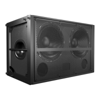
| width | 22.62" (575 mm) |
|---|---|
| height | 13" (330 mm) |
| depth | 17.50" (445 mm) |
| weight | 70 lbs (31.75 kg) |



 Loading...