Meyer Sound Laboratories, Inc.
2832 San Pablo Avenue
Berkeley, CA 94702
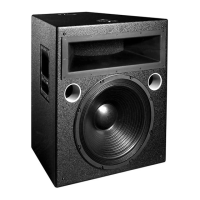
MSL-2A
Reinforcement
Loudspeaker
Operating Instructions
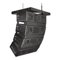
2. Multiple Cabinets. Each cabinet should
first be tested as above.
• Connect one loudspeaker and advance the
pink noise to a convienent level. Position
the measuring microphone between the
two adjacent loudspeakers, and about six
feet distant. Note the frequency response
and overall level.
• With the first loudspeaker connected, con-
nect the adjacent one and observe the ana-
lyzer. The entire curve should jump up in
level, indicating addition between the loud-
speakers. Polarity reversal between the
cabinets will cause severe broadband can-
cellation. As the cabinets are moved apart,
cancellation becomes less severe at high
frequencies. For this reason, polarity
should be tested with cabinets adjacent.
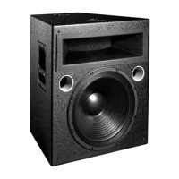
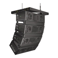
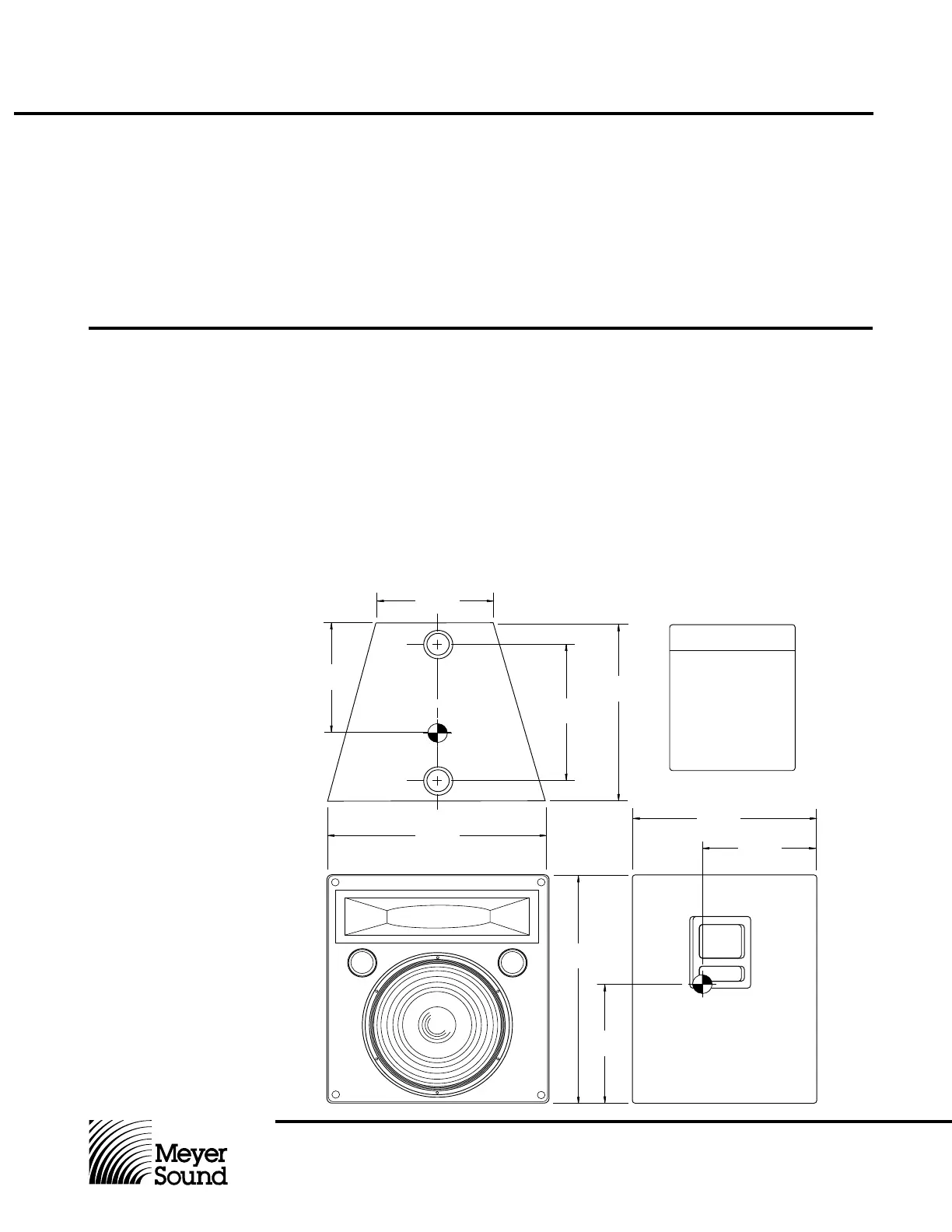
Rigging The MSL-2A loudspeaker has four steel rig-
ging brackets internally mounted as an inte-
gral part of the cabinet design and the cabinet
is supplied with either aircraft pan fittings (ring
and stud) or
3
¦8"-16 nut plates, according to
user preference. A flat plate is supplied when
no rigging hardware is specified. All three
plate types are held in place by six Phillips-
head machine screws and can be inter-
changed at any time. The handles on the
MSL-2A cabinet are provided for moving and
carrying the loudspeaker and are not to be
used for rigging purposes.
The rigging hardware is designed so that a
single point can support the normal load for
the cabinet. In the case of the MSL-2A, the
recommended maximum load is 420 lbs. (190
kg). Any of the individual rigging points are
capable of supporting this load with an ad-
equate saftey margin. However, Meyer Sound
strongly recommends that safety lines be run
to the other points. If the structural integrity of
any cabinet has been compromised by dam-
age or negligence, then the safety of the rig-
ging cannot be assured. All rigging should
be done by competent professionals.
18.25"
11.00"
12.75"
24.25"
18.25"
13.00"
21.25"
11.25"
Notes
Rigging Points
Top and Bottom
Grill (Not Shown)
Dimensions:
21.25" x 24.45" x 2"
Drawing Not To Scale
11.00"