Do you have a question about the Meyer Sound M SERIES and is the answer not in the manual?
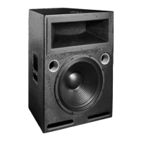
Details MICA's compact, self-powered three-way design, horizontal coverage, and peak output.
Explains the built-in 4-channel amplifier, power supply, and TruPower limiting for driver protection.
Covers MICA's QuickFly rigging, captive components, and splay angle adjustments for array configuration.
Highlights how MICA, MILO, and other Meyer Sound speakers integrate for optimal system performance.
Describes the Intelligent AC power supply features, connector types, and international voltage compatibility.
Outlines the safe operating voltage windows and maximum voltage tolerance for the MICA loudspeaker.
Details correct AC power distribution practices to prevent noise and damage.
Explains idle, long-term continuous, burst, and ultimate short-term peak current draw for circuit breaker selection.
Illustrates correct wiring for PowerCon, L6-20, IEC 309, and VEAM connectors for safety and performance.
Emphasizes the requirement for grounding, and precautions against electric shock.
Details the 10 kOhm balanced XLR input, wiring, and source device requirements for optimal SPL.
Explains how MICA's drivers are connected to the amplifier channels.
Describes the MPW-4/MICA amplifier, its class AB/H stages, and control card functions.
Covers Meyer Sound/VEAM and standard three-cable options, and strain relief fittings.
Explains TruPower limiting's advantage in measuring current and voltage for driver protection.
Details the TPL limiter for 10-inch drivers and its engagement via the Low Ch Limit LED.
Describes the TPL and peak limiters for compression drivers, indicated by the High Ch Limit LED.
Explains the forced-air cooling system, fan operation, and grille maintenance for optimal airflow.
Overview of the RMS user panel components: LEDs (Service, Activity, Wink) and buttons.
Indicates network operational status or local hardware failure.
Used to display an icon on the RMS screen or decommission the card.
Signals an ID signal sent from the host station computer to the loudspeaker.
Reboots the RMS card firmware code without changing commissioning state.
Indicates the loudspeaker is commissioned and operational on the network.
Describes the graphical Windows interface for monitoring loudspeaker status and performance.
Explains directivity achieved through constructive and destructive interference in line arrays.
Details MICA's drivers and Constant Q horns for coverage and directivity optimization.
Discusses MICA's high-frequency section, REM technology, and coverage patterns.
Explains coupling for vertical coverage and the effect of array length on low frequencies.
Factors for fine-tuning coverage: number of elements, vertical splay angles, and horizontal coverage.
Strategies for planning high-frequency coverage using element count and splay angles.
Focuses on mutual coupling and the effect of array length for low-frequency directionality.
Techniques for optimizing arrays using equalization channels and zones.
Addresses air absorption correction and near/mid-field frequency adjustments.
Integration of MICA with MILO arrays as downfill or sidefill.
Utilizing Galileo 616 and LD-3 for array optimization, atmospheric correction, and sub integration.
Guidelines for using DSPs with MICA, emphasizing phase shift and delay management.
Integration of MICA with subwoofers like 700-HP and 600-HP for extended low-frequency response.
Details integrating MICA with 700-HP subwoofers using Galileo and LD-3 filtering.
Explains integrating MICA with 600-HP subwoofers, covering flying and ground-stacking.
A cross-platform application for predicting coverage, response, and SPL of loudspeaker systems.
Instrumentation for acoustical system measurements, analysis, and alignment.
A dual-channel method for accurate measurements using any excitation signal.
Main applications of SIM: loudspeaker testing, alignment, and other acoustics analysis.
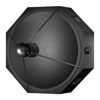
Describes MICA's captive rigging hardware and its role in flying, stacking, and transport.
Details the grid for flying MICA arrays and ground-stacking, with pickup point configurations.
Instructions for using the MG-MICA grid to securely ground-stack MICA enclosures or subwoofers.
Specifies pin positions for 0.5-degree uptilt and 2.5-degree downtilt when ground-stacking.
Adds fixed downtilt to ground-stacked MICA loudspeakers with additional adjustment.
Details pin positions for 0, 2.5, and 3.5-degree orientations relative to the grid.
Specifies pin positions for 0-degree orientation and 4-degree uptilt relative to the subwoofer.
Provides pin positions for 18.5 and 12.5-degree downtilt when using the MDTL-MICA link.
Specifies pin positions for 16 and 10-degree downtilt with the downtilt link and subwoofer.
Describes the caster frame for transporting MICA stacks and its positions for stability.
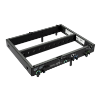
Step-by-step instructions for safely removing the amplifier module from the MICA cabinet.
Procedure for installing a new amplifier module, including connector alignment.
Guide on attaching the retainer strip and installing the rain hood for weather protection.
Provides operating frequency range, response, phase, SPL, dynamic range, and coverage details.
Details specifications for low/low-mid frequency drivers and high frequency compression drivers.
Lists input type, connectors, impedance, wiring, DC blocking, CMRR, RF/TIM filters, and sensitivity.
Specifies amplifier type, output power, THD/IM/TIM, load capacity, and cooling.
Details AC connector types, voltage selection, safety ratings, turn on/off points, and current draw.
Describes the RMS network configuration for reporting amplifier parameters.
Provides enclosure material, finish, grille, rigging, dimensions, and weight.
| Brand | Meyer Sound |
|---|---|
| Model | M SERIES |
| Category | Speakers |
| Language | English |