26
CHAPTER 7
The front links may be set in two different positions:
■ 0°: This is the standard position and it is used to
achieve between 0 and 6 degrees (adjusted on the rear)
for optimal acoustical performance.
■ 7°: This is the extended position to add 7 degrees to the
angles set on the rear link. These extended angles (7 to
13 degrees) can be use to extend the coverage or to
create a break in the array, for example, to miss balcony
fronts and other architectural obstacles.
Figure 7.4. MICA front GuideALinks, standard (0°) and extended (7°)
NOTE: Optimal acoustical performance for
MICA is achieved by using angles between 0
and 6 degrees in a MICA array; use extended angles
(7 to 13 degrees) with caution and only if necessary.
The rigid connections created by the QuickFly rigging
hardware allow easy adjustment of the array tilt, often
eliminating the need for pull-back straps in flown
configurations.
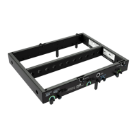
THE MG-MICA MULTIPURPOSE GRID
The MG-MICA multipurpose grid (Figure 7.6) allows multiple
MICA compact high-power curvilinear array loudspeakers to
be flown or ground-supported in numerous configurations.
In addition, the MG-MICA grid can be used with 600-HP
subwoofers that have been fitted with MRF-600 rigging
frames. The subwoofer’s MRF-600 GuideALink rigging is
directly compatible with MICA, and links to both the grid
and MICA enclosures using the same slots and pins.
CAUTION: For complete information on load
ratings and how to set up the MG-MICA and
other MICA rigging accessories, please use the MG-
MICA Assembly Guide (part number 05.147.034.01)
available on www.meyersound.com.
The MG-MICA grid can accommodate a variety of pickup
configurations using its six pick-up points — three on each
side of the frame.
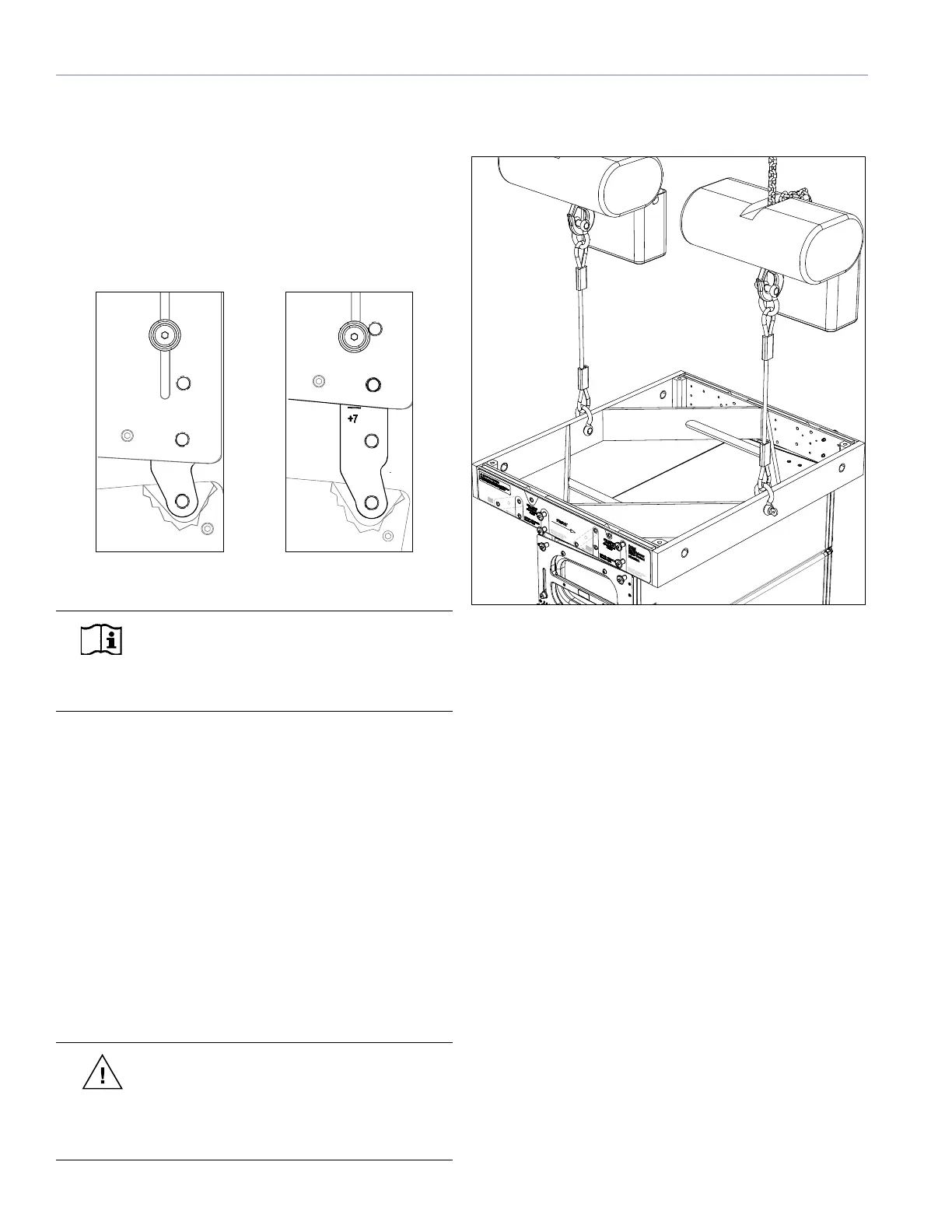
Figure 7.5. MG-MICA multipurpose grid is used to fly a MICA array
The MG-MICA grid allows you to fly MICA loudspeakers
in two positions with respect to the grid. The “rear flown”
position is most useful for achieving superior uptilt in the
grid and the “front flown” position helps achieving more
downtilt.
In flown configurations, the first MICA loudspeaker in the
array is always connected to the MG-MICA grid at the
0° position. The up and down tilt of the MG-MICA and
the complete array hung underneath can additionally be
adjusted using chain motors, or differing lengths of steel or
span set.
Using the MG-MICA for Ground-Stacking
In addition to its flown capabilities, the MG-MICA grid
forms a secure base for ground-stacking when the leveling
feet are installed. For ground-stacking, secure the bottom
MICA enclosure to the MG-MICA grid using the captive
GuideALinks and quick release pins.
MICA loudspeakers can be stacked by themselves on
the MG-MICA grid, or can be placed on top of 600-HP
subwoofers (fitted with the optional MRF-600 rigging
frames) pinned to the grid.

 Loading...