Do you have a question about the Meyer Sound DS-2P and is the answer not in the manual?
Explains the TPL system for speaker protection and performance optimization.
Explains how TPL LED indicates serious driver issues like short circuits.
Procedure for determining driver function or replacing a damaged driver.
| frequency response | ± 4 dB 50 – 160 Hz |
|---|---|
| phase response | ± 60° 60 – 200 Hz |
| maximum SPL (music as source) | 140 peak |
| maximum SPL (pink noise as source) | 136 dB continuous; 140 peak |
| dynamic range | > 120 dB |
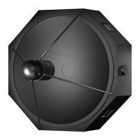
| coverage | 120° H x 120° V |
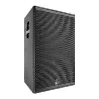
| low frequency transducer | Two 15" diameter MS-15 cone |
|---|
| input type impedance | 10 kΩ |
|---|---|
| connector | XLR (A-3) male and female |
| nominal input level | +4 dBu (1.23 Vrms) |
| amplifier type | Complementary power MOSFET output stages class AB/H |
|---|---|
| burst capability | 1240 Watts (620 Watts per channel) |
| THD, IM, TIM | < .02 % |
| connector | 250 V NEMA L6-20P / IEC 309 Twistlock male receptacle |
|---|---|
| automatic voltage selection | 85 – 134 V / 165 – 264 V; 50 Hz / 60 Hz |
| max continuous RMS current (115 V) | 8 A |
| max continuous RMS current (230 V) | 4 A |
| max continuous RMS current (100 V) | 10 A |
| max burst RMS current (115 V) | 15 A |
| max burst RMS current (230 V) | 8 A |
| max burst RMS current (100 V) | 18 A |
| max peak current during burst (115 V) | 22 Apk |
| max peak current during burst (230 V) | 11 Apk |
| max peak current during burst (100 V) | 25 Apk |
| soft-current turn-on inrush current | < 12A @115V |
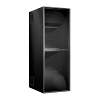
| dimensions | 21.25” W x 56.75” H x 30” D |
|---|---|
| weight | 221 lb (100 kg) |
| shipping weight | 267 lb (121 kg) |