Do you have a question about the Meyer Sound UPA-2P and is the answer not in the manual?
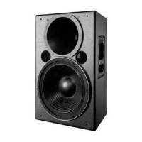
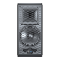
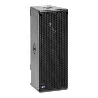
Describes the UPA-P's components: drivers, electronics, amplifier, and trapezoidal enclosure for various applications.
Explains beamwidth definition and Meyer Sound's constant-Q horn design for consistent coverage and minimal side lobes.
Details voltage range, PowerCon connector, Intelligent AC supply features, and brownout operation.
Provides a diagram and guidelines for AC cable wiring to create international or special-purpose power connectors.
Describes the rear panel slots for processor modules (Audio Input and Control, RMS) and blank plates.
Details three interchangeable input modules: standard looping, summing, and looping/polarity/attenuating.
Explains the 350 Wrms/ch amplifier, limiter functions to prevent over-excursion, and Limit LED indicators.
Describes natural convection cooling, heatsink temperature limits, On/Temp. LED, and optional fan kit.
Details the UPA-P weight, maximum load, safety factor, and available rigging bracket types.
Covers basic system concepts like polarity matching and array design principles for optimal coverage.
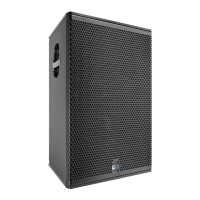
Illustrates system designs with subwoofers like USW-1P, including coverage examples.
Recommends Meyer SIM II Sound Analyzer and CP-10 Parametric Equalizer for system analysis.
Provides procedures to check driver polarity within a speaker and between adjacent loudspeakers.
Discusses low-frequency loading, VX-1 control, separate feeds, and optional input modules for level control.
Provides solutions for issues like no audio, hum/noise, distortion, compression, and overheating.
Advises on disconnecting power, using grounded receptacles, and proper wiring.
Covers avoiding moisture, foreign objects, overheating, direct sunlight, and internal high voltages.
Details the rear panel layout, including connectors, LEDs, and optional modules like RMS.
Provides detailed diagrams showing the top, back, side, and front views with dimensions.
A section for general notes or additional information.
Provides contact information for Meyer Sound Laboratories, Inc.
| Brand | Meyer Sound |
|---|---|
| Model | UPA-2P |
| Category | Speakers |
| Language | English |