DETACHING THE COMPLETE ASSEMBLY
Leave control switch in lower float position and push down on
the Lift Arm (4) approximately 1/4”. Disconnect the electrical
plug and slip on weather caps over the both ends. Remove
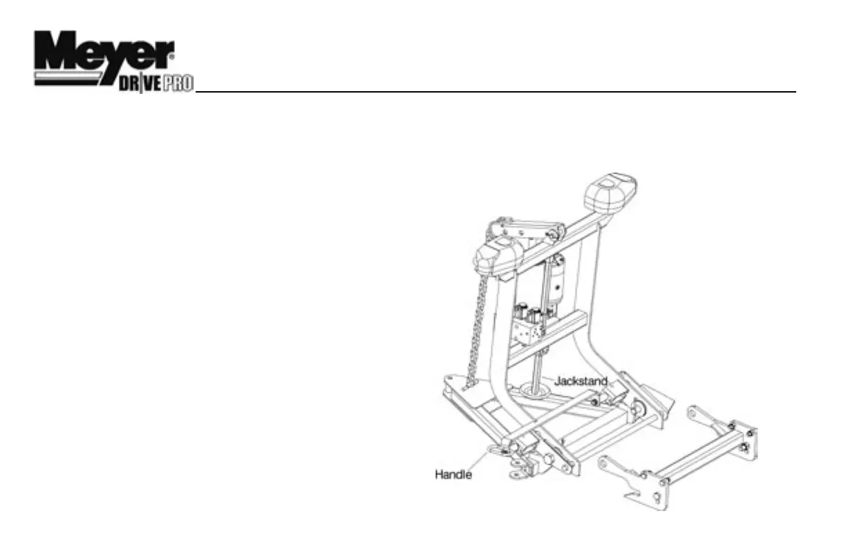
Safety Clip from jackstand. Push Jackstand Lever down,
until it is parallel with the cross bar of the Lift Frame, to lower
Jackstand to ground. At the same time push the top of the
Lift Frame up and towards the vehicle. Reinstall Safety Clip to
Jackstand below the lift frame. Pull, then rotate Handle so the
notch hooks onto the bracket on lift frame. The vehicle is now
free from mount and may safely back away.
ATTACHING THE COMPLETE ASSEMBLY
Check that the Handle Pin is disengaged. Drive the truck up
to the Drive ProTM assembly centering the hood of the truck
to the lift arm to assure proper alignment with lift frame guide
plates until contact is made. Once contact is made drive
forward, pushing the assembly a few inches. This insures
the A-Frame is square to the Clevis Frame for proper pin at-
tachment. The rear fixed Pins should now be aligned with the
rear notched hole on the clevis frame (1). Twist Handle Pin to
unlock so that the pins become spring loaded then push the
top of the Lift Frame towards the truck locking the front pins
to the clevis frame. Remove Safety Clip from jackstand. Push
Jackstand Lever down and raise Jackstand to storage posi-
tion. Reinstall Safety Clip to Jackstand above the lift frame.
Note: Wire Lynch Pin
(13) is used to Lock the
Jack Stand (3) in the
raised position once the
plow is attached to the
vehicle.
Caution: Crankstand
must be secured at all
times.
Reattach the one step
electrical connection.
4
™