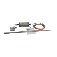
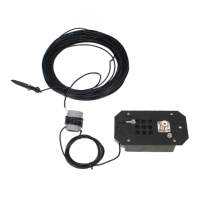
Tuning Procedure: The MFJ-2286 is a ground-mounted monopole, so tuning settings and SWR
are highly dependent on the characteristics of the counterpoise connected to the base block. For
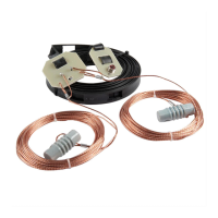
60 through 17 Meters, we suggest laying out four 12-foot insulated wire radials around the base.
A 50-foot roll of insulated wire is included with your antenna for making these four radials. Tuning
data is shown on the chart below:
Frequency E1 L1 Measured SWR
7.15 Full Length 3-3/8” 1.3:1 (radials)
10.11 Full Length 1-7/8” 1.3:1 (radials)
14.15 Full Length 5/8” 1:1 (radials)
18.11 13’ Shorted 1.4:1 (radials)
21.20 ~11’ Shorted --------------
24.93 ~ 9’ Shorted --------------
28.50 ~ 8’ Shorted --------------
50.10 ~4’ 6” Shorted --------------
All lengths for E1 include the whip plus coil assembly. "Shorted” means position the coil clip at the
top end of the coil so all turns are shorted out. For bands below 17-M, minor adjustments to coil
L1 may be required to achieve minimum SWR. For 15 through 6 Meters, the 12-foot radial kit may
not be optimal and the antenna mount alone may provide a sufficient counterpoise. To set up for
21 MHz and higher, simply set the element length shown on the chart, then increase or decrease
it until resonance falls in-band. Length may vary significantly, depending on the counterpoise.
Note that all tuning data was gathered with an in-line balun installed at the antenna to prevent the
coax shield from becoming part of the radial system and conducting RF back to the operating
position.
In Case of Trouble: If you are unable to obtain low SWR, if settings deviate widely from the
chart, or if SWR jumps intermittently, check the following:
[ ] Are the coil assembly and the whip seated firmly in the mount?
[ ] Is there damage to the coil or attachment wire?
[ ] Is the coax feed shorted, open, or intermittent?
[ ] (Above 20-M) Are all of L1’s turns bypassed by the slider?
[ ] Is your feedline impacting tuning? If so, ferrite beads or an inline balun will help.