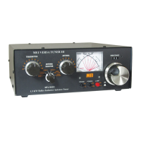
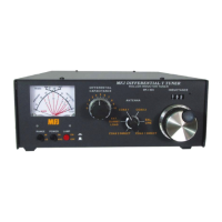
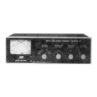
The MFJ-949B Deluxe Versa Tuner II is a versatile antenna tuner designed to match a wide range of transmitters to various antenna types, covering the 160 through 10-meter bands. This device is capable of handling up to 300 watts of RF output power from a transmitter.
Function Description:
The primary function of the MFJ-949B is to provide impedance matching between a transmitter and an antenna system, ensuring efficient power transfer and minimizing Standing Wave Ratio (SWR). It achieves this through adjustable inductance and capacitance controls.
A built-in SWR/wattmeter allows for the measurement of SWR, forward power, and reflected power in watts. This meter can be used in conjunction with the tuner or independently.
The unit also features an antenna selector switch, offering flexible connectivity options for different antenna configurations. Additionally, a 50-ohm dummy load is integrated into the tuner for convenient transmitter tuning.
For balanced line antennas, a 1:4 balun is incorporated, facilitating proper connection and operation.
Important Technical Specifications:
- Power Handling: Up to 300 watts of RF output power.
- Frequency Coverage: 160 through 10 meters.
- Dummy Load: 50 ohms, rated at 200 watts.
- Balun: 1:4 ratio for balanced lines.
- SWR Meter Sensitivity: Maximum sensitivity at approximately 5 watts.
Usage Features:
Installation:
The MFJ-949B should be installed between the transmitter and the antennas.
- Connect a coax line from the transmitter to the SO-239 coax connector labeled "TRANSMITTER" on the tuner.
- One or two coax-fed antennas can be connected to the SO-239 coax connectors marked "Coax 1" and "Coax 2." These can be connected directly to the transmitter, bypassing the tuner, by setting the ANT. SELECTOR to "Coax 1 Direct" or "Coax 2 Direct," respectively.
- A random wire antenna can be connected to the five-way binding post marked "WIRE." The random wire should be long, high, and clear of surrounding objects. For optimal operation, the length of the random wire antenna should be a quarter wave or longer of the operating frequency. The tuner must be well-grounded to the transmitter, with a five-way binding post marked "GROUND" provided for this connection. Do not ground the random wire antenna itself.
- A balanced line fed antenna can be connected to the two five-way binding posts marked "BALANCED LINE." A jumper wire from the "WIRE" binding post (as indicated by a dotted line on the MFJ-949B) couples the MFJ-949B to the balanced line through the 1:4 balun.
- Note: Only one of either a balanced line or a random wire antenna can be connected at a time. If a random wire antenna is used, ensure there is no jumper wire between "WIRE" and "BALANCED LINE."
Using the SWR/Wattmeter:
The meter can be used with or without the tuner.
- To use the meter without the tuner, set the Antenna SELECTOR to "Coax 1 Direct" or "Coax 2 Direct."
- To read forward RF output power, set the FUNCTION switch to "30" or "300" on "FWD." The meter will read a maximum of 30 watts on the "30" range and 300 watts on the "300" range.
- To read reflected power, set the FUNCTION switch to "30" or "300" on "REF."
- To read SWR:
- Turn the FUNCTION switch to "SET."
- While transmitting, adjust the SWR SEN. control for full meter scale deflection.
- Turn the FUNCTION switch to "SWR" to read the SWR.
- Important: For accurate SWR readings, the SWR SEN. control must be reset for full-scale deflection whenever the power level changes.
- The meter's maximum sensitivity is approximately 5 watts. For power less than 5 watts, the SWR will not read accurately. The minimum reading in the SWR position represents the minimum SWR.
- Note: The MFJ-949B's meter is not intended for precision measurement. For precision measurements, a dedicated precision meter should be used.
Tuning the MFJ-949B:
For optimal operation, the transmitter should be tuned for a 50-ohm output impedance for the operating frequency band.
- Set the ANT. SELECTOR switch to "Dummy Load" for initial transmitter tuning. Always tune the transmitter at a low output power.
- After properly tuning the transmitter, set the ANT. SELECTOR to the desired antenna.
- Set the TRANSMITTER and ANTENNA controls to 3.5 (capacitors half-opened).
- Rotate the INDUCTOR control until maximum noise is obtained with your transceiver in the receiving mode.
- Set the FUNCTION switch to "SET." Set the transmitter to the tune position and transmit.
- Turn the SWR SEN. control clockwise for a full meter scale deflection. If full-scale deflection cannot be obtained, increase the output power from the transmitter.
- Turn the FUNCTION switch to "SWR" for SWR reading.
- If the SWR is not 1:1, tune the MFJ-949B for a minimum SWR.
- While transmitting and with the INDUCTOR control set as in step 4, alternately adjust the TRANSMITTER and ANTENNA controls for a minimum SWR. These controls interact, so adjust them incrementally. Repeat until a minimum SWR is obtained.
- If a 1:1 SWR reading is not achieved, increase or decrease the INDUCTOR control one position and repeat step 9.
- Caution: If arcing occurs between capacitor plates, increase or decrease the INDUCTOR control one position and repeat step 9.
- If a 1:1 SWR cannot be achieved, repeat step 9 for each INDUCTOR control position. Perform this in tune mode or at low transmitter power.
- After achieving a minimum SWR, readjust the SWR sensitivity by turning the FUNCTION switch to "SET" and adjusting the SWR SEN. control. Then turn the FUNCTION switch to "SWR" to read SWR. The transmitter power can now be increased up to 300 watts. The SWR sensitivity must be reset again after full power is applied. The ANTENNA and TRANSMITTER controls may require fine adjustment for minimum SWR at high power.
- Note: This tuner will reduce the SWR of most antenna systems to nearly 1:1. In some cases, a 1:1 SWR may not be achievable. If this happens, try increasing or decreasing the length of the antenna. A 1.5:1 SWR results in only 4% reflected power, and a 2:1 SWR results in 11% reflected power.
- To read transmitter power, set the FUNCTION switch to "30" or "300" on "FWD."
- To read reflected power, turn the FUNCTION switch to "30" or "300" on "REF."
- A 1:1 SWR can occur from multiple control settings. When a 1:1 SWR is obtained, check the transmitter power to ensure it is relatively high. If the transmitter power has decreased substantially, try another INDUCTOR control setting and repeat step 9.
- When using the MFJ-949B for receiving only, tune it as described in steps 3 and 4.
Cautions:
- Do not continuously key the dummy load for more than 2 minutes at a time.
- Do not operate the antenna selector switch while transmitting.
- Do not use the MFJ-949B for over 300 watts of RF output power, even in the Direct Coax or Dummy Load positions.
Maintenance Features:
Warranty:
The MFJ-949B comes with a 12-month warranty from the date of purchase, covering defects in material and workmanship, provided the following conditions are met:
- Proof of Purchase: The purchaser must retain dated proof-of-purchase (bill of sale, canceled check, credit card or money order receipt, etc.) to establish the warranty claim. A copy of this proof must be submitted to MFJ Enterprises, Inc. at the time of warranty service. Alteration, erasure, or forgery of proof-of-purchase will void the warranty.
- Repair/Replacement: MFJ Enterprises, Inc. will repair or replace defective products at its option, free of charge, if returned postage prepaid with a personal check, cashier's check, or money order for $4.00 to cover postage and handling.
- Replacement Parts: MFJ Enterprises, Inc. will supply replacement parts free of charge under warranty upon request, with a dated proof-of-purchase and a $4.00 payment for postage and handling.
- Owner Repairs: The warranty is NOT void for owners who attempt to repair defective units. Technical consultation is available by calling (601) 323-5869.
- Exclusions: This warranty does not apply to kits sold or manufactured by MFJ Enterprises, Inc.
- PC Board Products: Wired and tested PC board products are covered only if the wired and tested PC board is returned. PC boards installed in the owner's cabinet or connected to switches, jacks, cables, etc., sent to MFJ Enterprises, Inc. will be returned unrepaired at the owner's expense.
- Liability: MFJ Enterprises, Inc. is not liable for consequential damages to person or property from the use of any MFJ product.
- Out-of-Warranty Service: MFJ Enterprises, Inc. will repair out-of-warranty products if delivered prepaid. All charges will be shipped COD to the owner.
- Implied Warranty: This warranty is given in lieu of any other express or implied warranty.
- Design Changes: MFJ Enterprises, Inc. reserves the right to make design or manufacturing improvements without obligation to install such changes on previously manufactured products.
- Service Address: All MFJ products for service (in-warranty or out-of-warranty) should be addressed to MFJ Enterprises, Inc., 921A Louisville Road, Starkville, Mississippi 39759, USA. A letter describing the problem in detail and a copy of the dated proof-of-purchase must accompany the unit.
- State Rights: This warranty provides specific rights, and other rights may vary from state to state.