MFJ-994B IntelliTuner Automatic Antenna Tuner Instruction Manual
© 2004-2010 MFJ Enterprises, Inc.
10
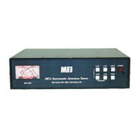
• Transmitter: SO-239 connector for coax cable from transceiver or amplifier.
• Ground: Wing-nut terminal for RF ground wire connection.
• Wire: Binding post for connecting single wire antenna. The WIRE binding post is internally
connected to the ANTENNA connector.
Note: When using the WIRE binding post, there should be no coax cable connected to the
ANTENNA connector.
• Antenna: SO-239 connector for coax cable from antenna. The ANTENNA connector is internally
connected to the WIRE binding post.
Note: When using the ANTENNA connector, there should be no wire attached to the WIRE
binding post.
Installation
WARNING
● Never operate the tuner with its cover removed. Contact with the components inside the
tuner while transmitting will result in painful RF burns.
● Locate the tuner so that the rear terminals are not accessible during operation. The single
wire connection may have high voltage while transmitting.
● Disconnect all antennas from the tuner during lightning storms.
● Always tune with low power (2-20 watts), and any in-line amplifier must be bypassed.
Apply maximum power only after tuning up.
● Never exceed tuner specifications.
1. Place the tuner in a convenient location at the operating position. When using a random wire antenna,
the feed through insulator can have high RF voltage. This voltage can cause serious RF burns if the
terminal is touched when transmitting. Be sure to locate the tuner so this terminal cannot
accidentally be contacted during operation.
2. Connect the tuner to the transceiver or amplifier with 50-ohm coaxial cable (such as RG-8/U). See
Figure 1 on page 4.
3. Connect the antenna to the tuner as follows:
• Coaxial feedline (RG-8/U or better) to the SO-239 connector labeled ANTENNA; or
• Random wire to the WIRE binding post on the back of the tuner. Note the back panel warning:
Do not connect WIRE and ANTENNA at same time!
Note: Route all random wire antennas safely to prevent RF burn hazard.
4. A GROUND post is provided for an RF ground connection. See “Grounding Hints” on page 16.
5. Connect a 12 to 15 VDC power source to the input jack labeled POWER.
 Loading...