________________________________________________________________
MFJ-204B Antenna Bridge Instruction and Technical Manual
- 7 -
THEORY OF OPERATION
Block Diagram
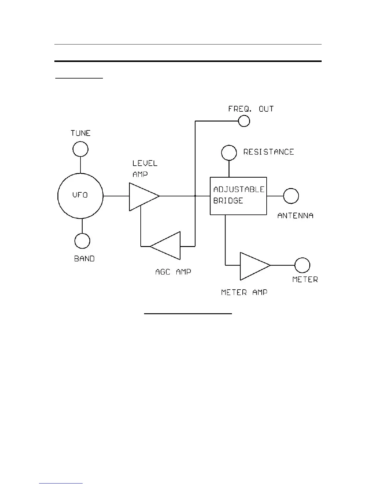
FIGURE 3: Block Diagram
Refer to Figure 3 and the Schematic diagram Figure 5 for this discussion of the theory of
operation. RF is developed in the VCO consisting of L1 through L10 and the associated
FETs Q1 and Q2 along with the variable capacitor. The Band Switch progressively
shorts out the inductors as the frequency range is increased. The RF is then passed to Q3
and amplified. This RF is sensed by D2 and the resulting voltage is fed to U2 where it is
amplified and fed to Q4. Q4 varies the voltage on the source of Q1 and Q2 maintaining
the stable RF level. The RF then goes to the bridge consisting of two fixed legs and one
variable leg the RESISTANCE Pot. The 4
th
leg of the bridge is the unknown leg which is
the Antenna input to the unit. When the bridge is unbalanced then D1 rectifies the
unbalanced voltage and this is amplified by U2 and deflects the meter. When the 4 legs
are equal in resistance then the meter nulls to zero and the Unknown resistance is equal to
the resistance shown by the RESISTANCE pot.