MFJ-259C Instruction Manual HF/VHF SWR Analyzer
16
[ ] Tune the VFO higher in frequency to find the next X=0 null (or close as possible to 0).
[ ] Press Gate to enter second frequency. Display will show:
[ ] Multiply DTF x Velocity Factor of the cable (Vf) to get the physical distance in feet.
(64.0 x .66 = 42.24)
The cable length (or the distance to a "fault" in a longer cable) is 42.24 feet, or 42' 3".
5.6 Resonance Mode: Resonance mode works exactly the same as R&X in the Basic Menu,
except the analog Impedance Meter displays Reactance rather than Impedance Magnitude.
This change makes it easier to spot nulls and pinpoint the frequencies where Resonance
occurs. Resonance is defined as the frequency where Capacitive Reactance (Xc) and
Inductive Reactance (XL) cancel out and equal zero (X=0).
To access Resonance Mode:
[ ] Connect the DUT to the Antenna jack
[ ] Enter Advanced Mode
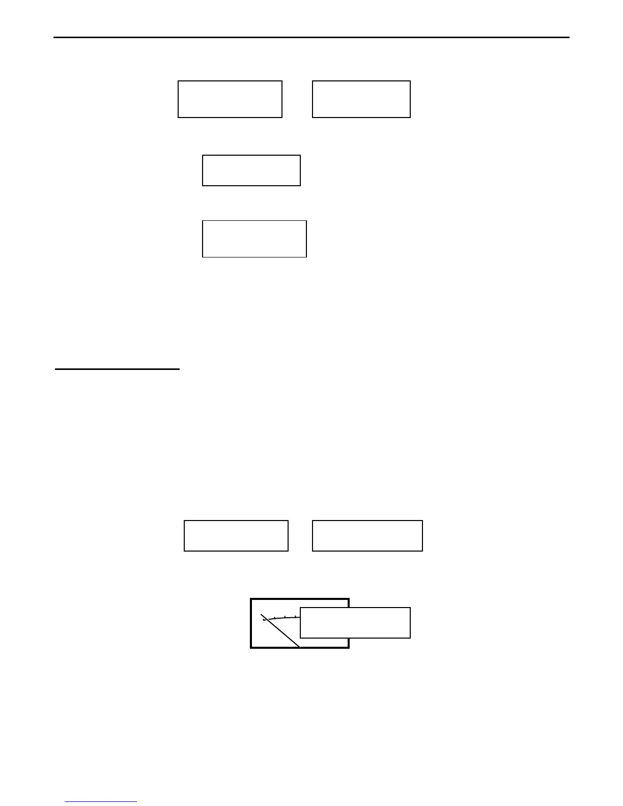
[ ] Press Mode three times to access Resonance Mode and wait for the working screen:
[ ] Watching the Impedance meter, tune for a null (X=0 or as close as possible).
Ohms
40
50
70 100
400
0
10
20
Accuracy Note: When measured thought feedline, the X=0 reading many not occur on the
frequency where the antenna is actually resonant. As with any reactance measurement, the
analyzer Calibration Plane must be positioned close to the DUT (or to 0-degrees of phase
rotation) as possible.
3.8944 MHz 1st
DTF X=0
Dist. to fault
64.0 ft x Vf
3.8944MHz 2nd
DTF X=0
11.519 MHz 2nd
DTF
=2
Resonance Mode
tune for X=0
14.150 MHz 1.5
R=54 X=4 SWR
14.168 MHz 1.5
R=54 X=0 SWR