MFJ-259C Instruction Manual HF/VHF SWR Analyzer
8
with all harmonics suppressed below -25 dBc. Although not phase-locked, stability is adequate
for most general alignment applications. To protect the bridge diodes from accidental DC
voltage applications, we strongly recommend installing an in-line attenuator or coupling
capacitor to provide isolation.
4.0 Basic Measurement Modes
4.1 The Basic Operating Menu:
The MFJ-259C Basic Menu presents the analyzer's most
frequently used measurement functions. Tap the Mode switch to step through each one -- or
hold it down to scroll through them at a 3-second-per-screen rate. Selections are:
1. R&X: Measures SWR, R (Resistance), X (Reactance), Z (Z-magnitude), and (Phase).
2. Coax Loss (dB): Measures loss at any given frequency for 50-Ohm coax or a DUT.
3. Capacitance (pF): Measures component's reactance, computes capacitance.
4. Inductance (uH): Measures component's reactance, computes inductance.
5. Frequency (MHz): Counter mode, measures frequency of an external RF source
Each menu selection opens with an Identifier Screen*. After a brief pause, a Working Screen
appears to present data. The menu is circular, reverting back to the beginning.
*On analyzer boot-up, the R&X Working Screen appears without its identifier screen. However,
the Identifier Screen will appear when stepping or scrolling through the menu:
4.2 Measuring SWR, R, X, Z, and
: This default function measures and displays five of the
most widely used network parameters simultaneously. To access and view measured data for
SWR, R, X, Z, and , follow the checklist below:
[ ] Turn on the analyzer and allow it to boot to the default mode (R&X).
[ ] Adjust the Frequency switches and Tune control to the desired test frequency (MHz).
[ ] Connect the feedine (or load) to the analyzer's Antenna jack.
[ ] Read numerical Standing Wave Ratio (SWR) in the upper right-hand corner of the display:
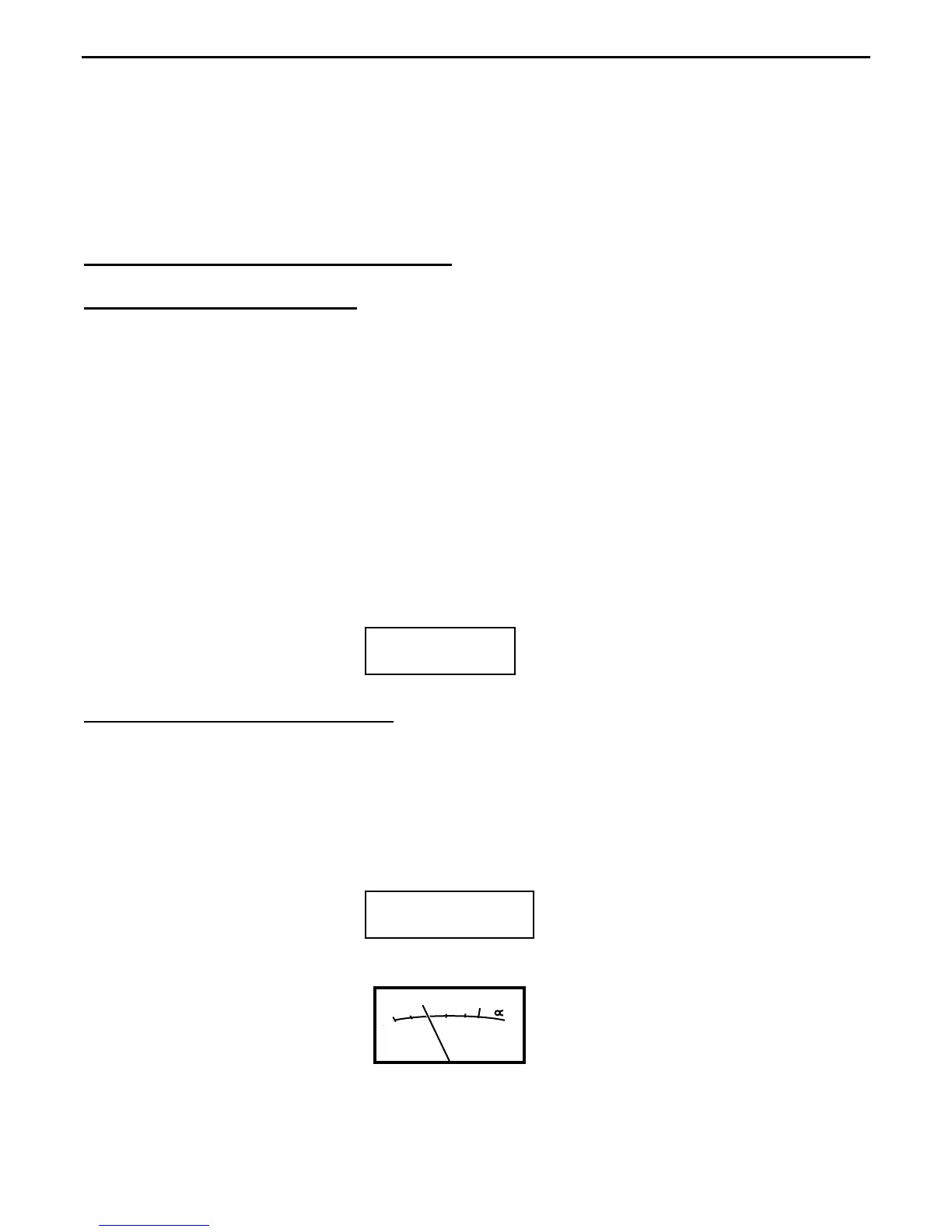
[ ] Also, read SWR on the analog panel meter display:
SWR
3
2.5
2.0
1.5
1.2
1
[ ] Read Complex Impedance (R and X) on the bottom line of the display:
10.120 MHz 1.5
R= 73 X=5 SWR
Impedance
R &