Do you have a question about the MFJ MFJ-4275MV and is the answer not in the manual?
Lists the five types of output terminals and their respective current ratings.
Details the adjustable output voltage range from 4 Vdc to 16 Vdc with a detent at 13.8 Vdc.
Instructions for setting the correct input AC voltage for operation (115V or 230V).
Steps to adjust and set the desired output voltage using the variable control.
Guidance on connecting devices to output connectors and initial power-on.
Explains protection against output shorts, overloads, over-voltage, and overheating.
Details the built-in battery charging circuit with fixed 13.8 Vdc output.
Instructions for preparing connector housings and wires for assembly.
Guidance on properly crimping or soldering wires to terminals for reliable connections.
Steps for correctly inserting the assembled terminals into the connector housing.
Outlines requirements for retaining proof-of-purchase and submitting warranty claims.
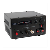
The MFJ-4275MV is a versatile switching power supply designed to provide reliable DC power for various electronic devices. Its primary function is to convert AC input voltage into a stable DC output, suitable for powering a wide range of equipment. The unit is engineered to deliver substantial current, making it suitable for demanding applications.
The core function of the MFJ-4275MV is to supply direct current (DC) power. It achieves this by taking alternating current (AC) from a standard wall outlet and converting it into a regulated DC output. This conversion process is crucial for electronic devices that require a stable and consistent DC power source to operate correctly. The power supply is designed to handle significant power demands, offering both intermittent and continuous current capabilities. This flexibility allows it to support devices with varying power requirements, from those needing short bursts of high current to those requiring a steady, continuous supply.
A key feature of the MFJ-4275MV is its integrated battery charging circuit. This allows the unit to not only power devices but also to charge compatible batteries. The charging function is specifically designed to provide a controlled charging current, ensuring efficient and safe battery replenishment. This dual functionality makes the power supply a valuable tool for users who need to both power their equipment and maintain their battery-powered devices.
The power supply incorporates multiple output terminals, providing flexibility in connecting various devices. These terminals are designed to accommodate different types of connectors commonly used in electronic setups, ensuring broad compatibility. The inclusion of a variable output control allows users to adjust the output voltage, catering to the specific voltage requirements of different devices. This adjustability is critical for preventing damage to sensitive electronics that might be incompatible with a fixed voltage output.
The MFJ-4275MV is designed with user convenience and safety in mind, offering several features that enhance its usability.
Versatile Output Connections: The power supply is equipped with a variety of output terminals to suit different connection needs. These include two sets of Anderson Powerpole® connectors, two sets of 5-way binding posts, two sets of quick connect terminals, and a cigarette lighter socket. This diverse array of connectors ensures that users can easily connect a wide range of devices without needing additional adapters. The Anderson Powerpole® connectors, in particular, are known for their robust and secure connections, ideal for mobile and amateur radio applications.
Adjustable Output Voltage: A prominent feature is the variable output control, which allows users to adjust the DC output voltage from 4 Vdc to 16 Vdc. This adjustability is crucial for compatibility with devices that operate at different voltage levels. The control also includes a pre-set detent position, which conveniently sets the output voltage to 13.8 Vdc. This specific voltage is commonly used in amateur radio and other DC-powered applications, making it easy for users to quickly set the power supply to a standard operating voltage.
Battery Charging Capability: The built-in battery charger circuit is a significant usage feature. It allows users to charge batteries directly from the power supply. The charging output is fixed at 13.8 Vdc, providing a consistent voltage for battery charging. The circuit is designed to manage charging current, initially providing a higher current for faster charging and then reducing it to a trickle charge as the battery approaches full capacity. This intelligent charging mechanism helps prevent overcharging and prolongs battery life. The battery to be charged must be connected to the dedicated charger output binding posts located on the back of the unit.
Ease of Installation: Before initial use, users are instructed to ensure the correct AC input voltage setting (115V for 100/110/120 AC or 230V for 200/220/240 AC). The default factory setting is 115V. This step is critical for safe operation and to prevent damage to the unit. The installation process is straightforward: connect the power supply to an AC outlet, turn it on, adjust the output voltage using the variable control, then turn it off before connecting any loads. Once loads are connected, the power supply can be turned on again. This sequence ensures that devices are not subjected to voltage fluctuations during startup or adjustment.
Anderson Powerpole® Connector Assembly: For users utilizing the Anderson Powerpole® connectors, detailed assembly instructions are provided. These instructions guide users through the process of preparing wires, inserting them into terminals, and assembling the connector housings. The manual emphasizes the importance of secure connections, whether through crimping or soldering, to ensure optimal performance and minimize resistance. This attention to detail in the assembly process helps users achieve reliable and safe connections.
The MFJ-4275MV incorporates several protection mechanisms to ensure its longevity and safe operation, effectively acting as maintenance features by preventing damage.
Fault Protection: The power supply is equipped with comprehensive fault protection. This includes safeguards against output terminal short circuits, overloads (exceeding the rated current), over-voltage (pre-set at 16 Vdc), and component overheating. These protections are crucial for preventing damage to both the power supply and the connected equipment.
Automatic Shutdown and Warning LED: In the event of any fault condition (short circuit, overload, over-voltage, or overheating), the power supply will automatically shut off. This immediate shutdown prevents further damage. A warning LED will illuminate to indicate that a fault has occurred, alerting the user to the issue.
Reset Procedure: To reset the power supply after a fault, users simply need to turn the unit OFF, wait for 20 seconds, and then turn it back ON. This reset procedure allows the internal protection circuits to clear and the unit to resume normal operation, provided the fault condition has been resolved. This simple reset mechanism ensures that the power supply can be quickly brought back online after a protective shutdown.
Robust Construction Guidance (Anderson Powerpole®): While not a direct maintenance feature of the power supply itself, the detailed instructions for assembling Anderson Powerpole® connectors contribute to the overall reliability and longevity of the connections. By guiding users to create good, solid connections through proper crimping or soldering, the manual helps prevent issues like loose connections, high resistance, and potential arcing, which could otherwise lead to equipment damage or poor performance. The emphasis on not damaging wire strands, properly inserting wires, and maintaining the terminal body's shape ensures that the connectors perform optimally and last longer.
These features collectively contribute to the MFJ-4275MV's reliability and ease of use, making it a robust and user-friendly power solution for a variety of applications.
| Input Voltage | 115/230 VAC |
|---|---|
| Output Voltage | 13.8 VDC |
| Output Current (Continuous) | 25 A |
| Output Current (Surge) | 30 A |
| Cooling | Fan Cooled |
| Output Connector | Binding Posts |
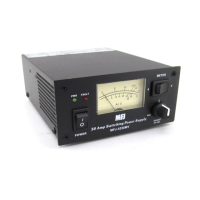
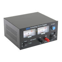
| Metering | Analog meters for voltage and current |