MFJ-5124K/Y Radio Interface Instruction Manual
2 © 2005-2010 MFJ Enterprises, Inc.
Jumper Settings
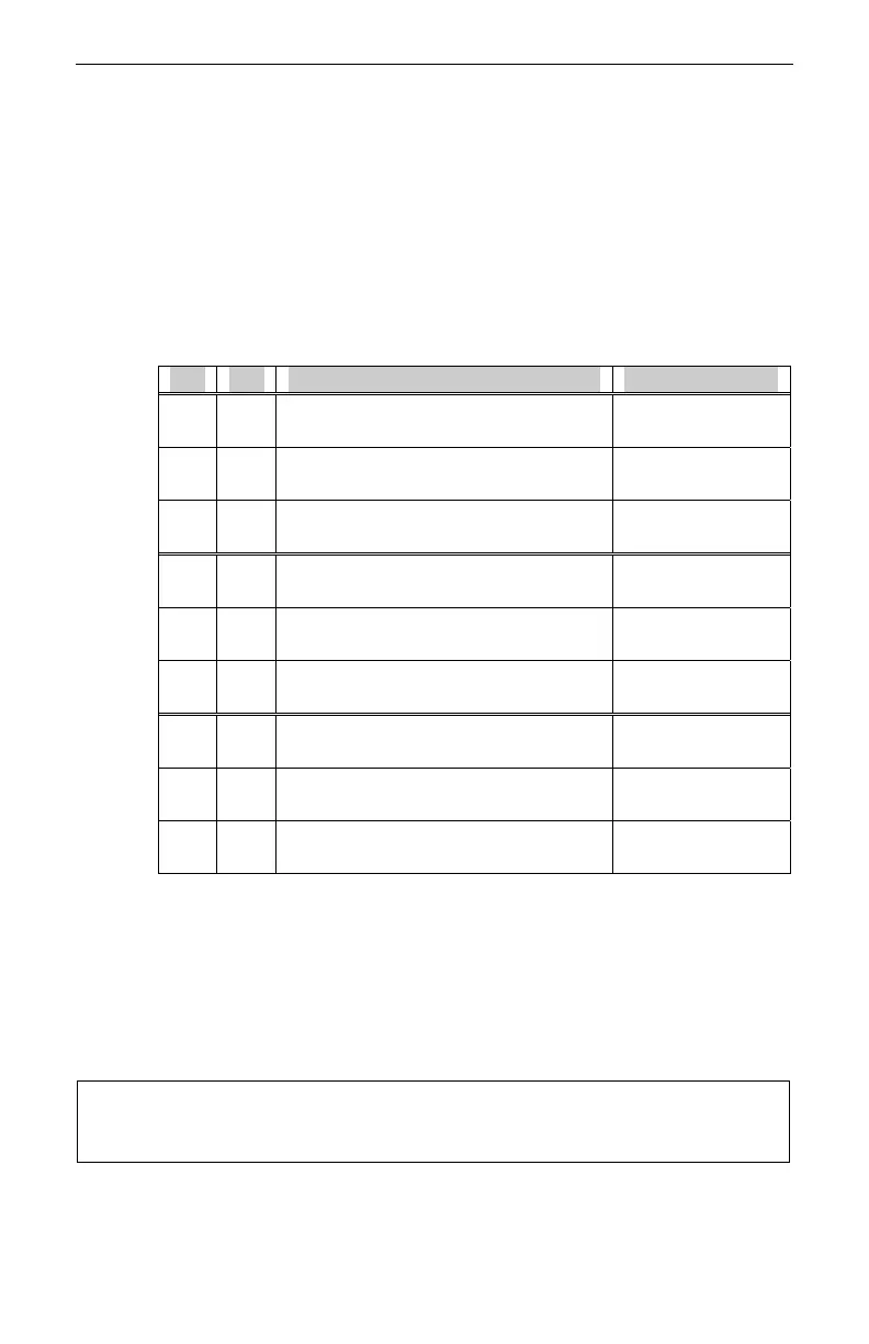
Two jumpers, JP1 and JP2, inside the MFJ-5124 are used to select the radio to
interface with. To change these jumper settings:
1. Disconnect the MFJ-5124 from the radio and the tuner.
2. Open the MFJ-5124 case by removing the two screws on the bottom.
3. Configure jumpers JP1 and JP2 according to the following table to
select the radio to interface with.
JP1 JP2 To Interface Using
A A
Kenwood (auto detected tuner)
†
such as TS-570S, etc.
MFJ-5124K
(6-pin molex)
A B
Kenwood (menu enabled tuner)
such as TS-450S, TS-690S, etc.
MFJ-5124K
(6-pin molex)
A C Firmware Version Number N/A
B A
Yaesu TUNER interface
‡
FT-100, -450, -857, -897, -950
MFJ-5124Y
(8-pin mini DIN)
B B Reserved for future use. N/A
B C Reserved for future use. N/A
C A
Yaesu CAT interface
FT-100
MFJ-5124Y
(8-pin mini DIN)
C B
Yaesu CAT interface
FT-857, FT-897
MFJ-5124Y
(8-pin mini DIN)
C C
Yaesu CAT interface §
FT-847
MFJ-5124Y2
(DB-9)
† MFJ-5124K factory default.
‡ MFJ-5124Y factory default.
§ MFJ-5124Y2 factory default.
4. Close the MFJ-5124 case and secure with the two screws.
5. Refer to the appropriate section in this manual to connect the MFJ-5124
to the radio and the tuner.
Note: The Yaesu TUNER interface allows the use of the radio’s (TUNE)
key to initiate automatic tuning, whereas the Yaesu CAT interface
uses the tuner’s [TUNE] button to start automatic tuning.


 To Next Page