Do you have a question about the MFJ Super Hi-Q Loop MFJ-1786 and is the answer not in the manual?
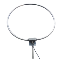
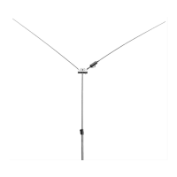
How to mount the antenna for vertical polarization.
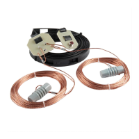
How to mount the antenna for horizontal polarization.
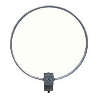
Details vertical polarization pattern and radiation.
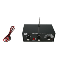
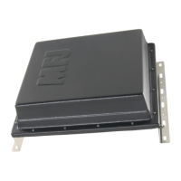
Power requirements and connections for the control head.
Procedure for tuning when the last frequency is unknown.
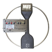
The MFJ Super Hi-Q Loop™ Antenna is a high-performance, small-space antenna designed for amateur radio enthusiasts. It offers excellent performance and convenience for its size.
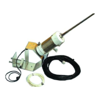
The MFJ Super Hi-Q Loop™ Antenna is a magnetic loop antenna that functions as both a transmitting and receiving antenna. Its primary purpose is to provide efficient radio frequency (RF) communication in a compact form factor, making it suitable for situations where a full-size dipole antenna is impractical. The antenna features a semi-automatic tuning unit that allows for easy adjustment to different frequencies. This tuning unit, along with control voltages, is coupled to the antenna through the coaxial feedline, simplifying installation with a single wire. The antenna is designed to minimize resistive losses, which is crucial for the efficiency of small loop antennas. It achieves this by using thick-walled, large-diameter round aluminum pipe for the radiating element and heli-arc welding all current-carrying joints to eliminate high-resistance pressure contacts. A specially constructed butterfly capacitor, also arc-welded, further reduces loss resistance compared to conventional air variable capacitors.
The antenna's control head includes a cross-needle SWR-WATTMETER, which displays forward and reflected power on both high and low power scales. The high power scales are 300 watts forward and 60 watts reflected, while the low power scales are 30 watts forward and 6 watts reflected. Power readings are always taken from the top scale with a 0.1 multiplier in low power mode. The control head supplies the necessary control voltages to the loop antenna via the coaxial feedline. These voltages are low voltage and low current, ensuring that the length of the coaxial line does not significantly impact motor operation. The control head also incorporates circuits that detect the antenna's tuning condition, activated when the AUTO BAND SELECT "UP" or "DOWN" buttons are pressed. When these switches are "latched" in the presence of constant RF, the loop automatically tunes until the SWR drops or the end of the tuning range is reached. A "beeper" sounds when the SWR minimum is crossed, and the motor voltage is removed. If the end of the range is reached without crossing the SWR minimum, the FREQ "UP" or "DOWN" LED extinguishes, and the motor stops. After releasing the "latched" button, a "MOVE" LED near the "FINE TUNE" buttons illuminates, indicating the direction for fine-tuning. The control head also allows for slow, stepped motor movements using the FINE TUNE buttons to optimize SWR. The "MOVE" LEDs extinguish after the correct FINE TUNE button is pressed. Additionally, the control head features switches for wattmeter power sensitivity, meter lamp, and main power on/off. Two yellow LEDs, labeled "FREQ" UP and DOWN, monitor the current drawn by the loop motor (feedline). A continuous light indicates that an "AUTO BAND SELECT" switch is active and the motor is running, while a flashing LED indicates a FINE TUNE switch is active. These LEDs should extinguish within 40 seconds of fast tuning once the motor stops.