EasyManua.ls Logo

MFJ VERSA TUNER II - Installation; Tuner Placement; Antenna Connections

MFJ VERSA TUNER II
6 pages
Print Icon
To Next Page IconTo Next Page
To Previous Page IconTo Previous Page
Loading...
www.SteamPoweredRadio.Com
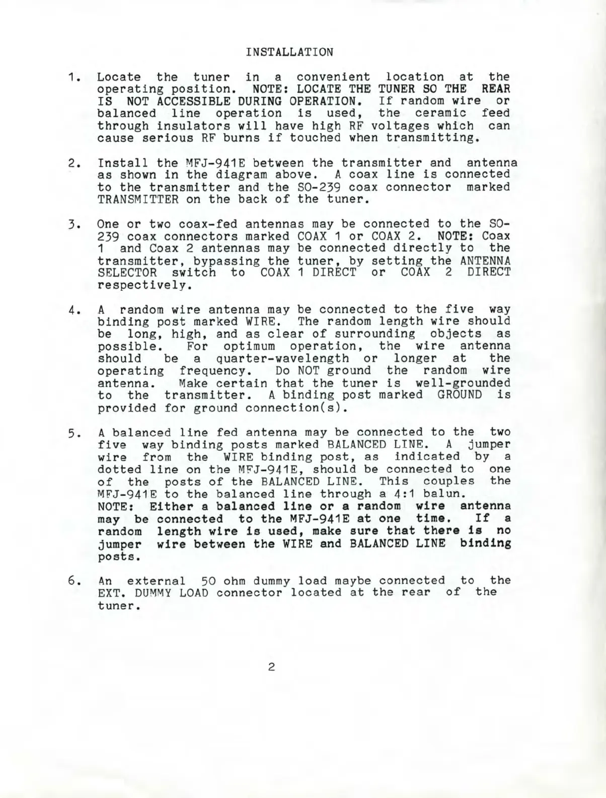
INSTAL
L
ATION
1.
Locate
the
tuner
in
a
convenient
location
at
the
operating
position.
N
OTE:
LOCATE
THE TUNER SO
THE
REAR
IS N
OT
A
CCESS
I BLE
DURI
NG
OPE
RA
TION
.
If
r andom wir e
or
balanced
line
operation
is
used
,
the
ce
ramic
fe
ed
th
r
ough
insu
l
ators
wil l
have
high
RF
voltages
which
can
cause
serious
RF
burns
if
touched
when t r
ansmitting
.
2.
In
sta
l l
the
MFJ
- 941E
between
the
t r
ansmitter
and
antenna
as
shown
in
the
diag
r
am
above
. A
coax
line
is
connected
to
the
t r
ansmitte
r and
the
S0- 239
coax
connector
marked
TRANSMITTER
on
the
back
of
the
tuner.
3.
One
or
two
coax
-
fed
antennas
may
be
connected
to
the
S0-
239
coax
connectors
marked
COAX
1 or
COAX
2.
NO
TE: Coax
1 and Coax 2
antennas
may
be
connected
di
r
ectly
to
the
t r
ansmitte
r ,
bypassing
the
tuner
, by
setting
the
ANTENNA
SELECTOR
switch
to
COAX
1
DIRECT
or
COAX
2
DIRECT
r
espectively
.
4. A r andom
wire
antenna
may
be
connected
to
the
five
way
binding
post
ma
r
ked
WIRE
. The r andom
length
wire
should
be
l
ong,
high,
and
as
clear
of
sur
r
ounding
objects
as
possible.
Fo
r optimum
operation
,
the
wire
antenna
should
be
a
quarter
-
wavelength
or
longer
at
the
operating
frequency
.
Do
NOT
ground
the
random
wire
antenna
.
Make
ce
r
tain that
the
tuner
is
well
- gr
ounded
to
the
transmitter.
A
binding
post
marked
GROUND
is
provided
for
ground
connection(s).
5.
A
balanced
line
fed
antenna
may
be
connected
to
the
two
five
w
ay
binding
posts
marked
BAL
ANCED
LINE. A
jumper
wire
from
the
WIRE
binding
post
,
as
indicated
by
a
dotted
line
on
the
MFJ
-
941E,
shou
l d
be
connected
to
one
of
the
posts
of
the
BALANCED
LINE.
This
couples
the
MFJ-941E
to
the
balanced
line
through
a
4:1
balun.
NOTE
: E
ither
a
balan
c
ed
line
or
a
rand
om
wire
antenn
a
m
ay
be
conne
c
te
d t o
the
MFJ
-941E
at
one
time.
If a
r andom
len
gt
h w
ire
i s
used,
make
sure
t h
at
t
here
is
no
jum
per
wire
bet
w
een
t he WI
RE
an
d B
ALA
NCE
D L
INE
binding
po
sts
.
6.
An
external
50
ohm
dummy
load
maybe
connected
to
the
EXT.
DUMMY
LOAD
connector
located
at
the
rear
of
the
tune
r.
2