4‐ControlUnitE6L/Rev6.11
2.GENERALSAFETYINSTRUCTIONS
Targetgroup
• Onlyqualifiedandtrainedelectriciansmayconnect,
programmeandservicethecontrols.Qualifiedand
skilledelectriciansmust:
• Haveknowledgeofthegeneralandspecificandacci‐
dentpreventionregulations.
• Haveknowledgeoftherelevantelectricalregula‐
tions.
• Betrainedintheuseandcareofappr
opriatesafety
equipmentandclothing.
• Becapableofrecognisingthedangersassociated
withelectricity.
Instructionsforinstallationandconnection
• Beforecomm encing electricalworks,thesystem
mustbedisconnectedfromtheelectricitysupply.
Measuresmustbetakenthattheelectr i citysupply
remainsdisconnectedforthedurationoftheworks.
• Lo
calsafetyregulationsmustbeobserved.
• Mainscablesmustbelaidseparatelyfromcontrol
cables.
3.1.PRODUCTDESCRIPTION
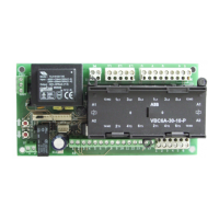
ThecontrolunitE6LisOVITOR’sbasiccontrolunitforauto‐
maticdoorsandgates.ThecontrollogicoftheE6Lhas
beenimplementedbysoftware.Thesafetycircuitsare
connecteddirectlyinseries withthemotorcontroltoen‐
surethatnofunctionrelatedtosafetydependsonthe
modeofthepr
ogramortheelectroni cs.Inthebasic ver‐
sion,themotorcontro ltakesplacebycontactors,butspe‐
cialarrangementsalsoenableotherkindsofmotorcon‐
trol,suchasinputthroughafrequencyinverter.Itispossi‐
bletoextendthebasicversionbyinstallingboardsforpe‐
rip
heraldevicesorcomplementaryfunctionsontoprein‐
stalledplug‐insockets.Thereisasocketonthebasicboard
foraradioreceiveraswellas foranaddi tionalsafetypho‐
tocellboard.Otherextr aboardsaretobeinstalledinto
threebusterminals.Ordinarybasicsettings,suchasthe
del
ayofautomaticclosingandthedurationoftherunning‐
timelimiter,aredonebymeansofrotaryswitchesonthe
board.Certainbasicmattersrelatedtothemodeofopera‐
tioncanbesetwithaDIP‐typeselectorswitchandshort‐
circuitplugsontheboard.
Thelight‐em
ittingdiodes(LED)indicatingtheoperating
modeoftheperipheraldevicesaresituatedabovetheter‐
minalblock;theope ratin gmodesoftheprogramandof
theprocessorcanbeobservedontheLED’softheboard.
Thecontrolsystemcanbeusedfor checkingthecondition
oftheusedequ
ipmentandthedooritself,testingthe
safetyedgeandsafetyphotocellandcheckingthecondi ‐
tionofthedoorbalancewiththeloadcontrol.
Thecontrolsystemalso takesaccountofoperations
neededduringafirealarmifthedoorisusedasafire
door.
3.OVERVIEWOFPRODUCT



 To Next Page