EasyManua.ls Logo

MG ACV User Manual

MG ACV
3 pages
To Next Page IconTo Next Page
Page #1 background imageLoading...
Page #1 background image
BEFORE USE ....
Thank you for choosing us. Before use, please check con-
tents of the package you received as outlined below.
If you have any problems or questions with the product,
please contact our sales office or representatives.
PACKAGE INCLUDES:
DC alarm (body + base socket + input resistor) ................(1)
Input resistor is provided only with current input type.
MODEL NO.
Confirm Model No. marking on the product to be exactly
what you ordered.
INSTRUCTION MANUAL
This manual describes necessary points of caution when
you use this product, including installation, connection and
basic maintenance procedures.
POINTS OF CAUTION
POWER INPUT RATING & OPERATIONAL RANGE
Locate the power input rating marked on the product and
confirm its operational range as indicated below:
AC power: Rating ±10%, 50/60 ±2 Hz, approx. 2VA
DC power: Rating ±10%, approx. 2W
or 85 – 150V, approx. 2W for 110V rating
GENERAL PRECAUTIONS
Before you remove the unit from its base socket or mount
it, turn off the power supply and input signal for safety.
ENVIRONMENT
Indoor use.
When heavy dust or metal particles are present in the
air, install the unit inside proper housing with sufficient
ventilation.
Do not install the unit where it is subjected to continuous
vibration. Do not subject the unit to physical impact.
Environmental temperature must be within -5 to +60°C
(23 to 140°F) with relative humidity within 30 to 90% RH
in order to ensure adequate life span and operation.
WIRING
Do not install cables close to noise sources (relay drive
cable, high frequency line, etc.).
Do not bind these cables together with those in which
noises are present. Do not install them in the same duct.
AND ....
The unit is designed to function as soon as power is sup-
plied, however, a warm up for 10 minutes is required for
satisfying complete performance described in the data
sheet.
COMPONENT IDENTIFICATION
A•UNIT
LIMIT ALARM
SET.1
SET 1 ADJ
HYSTERESIS
(DEADBAND)
SET 2 ADJ
SET.2
Body
Base Socket
Specifications
Input Resistor
FRONT PANEL CONFIGURATION
No.1 LED
No.1
Deadband (Hysteresis) Adj.
No.2
Deadband (Hysteresis) Adj.
No.2 LED
No.1 Setpoint Adj.
No.2 Setpoint Adj.
Zero Adj.
Span Adj.
Span Adj.
Zero Adj.
• No. 1 Setpoint Adj.
Used for adjusting No. 1 alarm setpoint.
• No. 1 LED
Turns on when No. 1 alarm is tripped.
• No. 1 Deadband (hysteresis) Adj.
Used for adjusting No. 1 deadband (hysteresis) within 1 –
100%.
• No. 2 Deadband (hysteresis) Adj.
Used for adjusting No. 2 deadband (hysteresis) within 1 –
100%.
• No. 2 LED
Turns on when No. 2 alarm is tripped.
• No. 2 Setpoint Adj.
Used for adjusting No. 2 alarm setpoint.
DC ALARM
MODEL
ACV
EM-2117 Rev.9 P. 1 / 3
MG CO., LTD. www.mgco.jp
5-2-55 Minamitsumori, Nishinari-ku, Osaka 557-0063 JAPAN
INSTRUCTION MANUAL
Question and Answer IconNeed help?

Do you have a question about the MG ACV and is the answer not in the manual?

MG ACV Specifications

General IconGeneral
BrandMG
ModelACV
CategorySecurity System
LanguageEnglish

Summary

Before Use

Package Includes

Details the items included in the DC alarm package, including the body, base socket, and input resistor.

Model No.

Instructions to confirm the model number marking on the product matches the order.

Instruction Manual

Outlines the manual's content, covering installation, connection, and basic maintenance procedures.

Points of Caution

Power Input Rating & Operational Range

Specifies the power input rating and operational voltage/frequency ranges for AC and DC power.

General Precautions

Advises turning off power and signal before removing or mounting the unit for safety.

Environment

Details environmental conditions for installation, including temperature, humidity, dust, and vibration.

Wiring

Provides guidance on wiring practices, particularly regarding noise sources and cable routing.

And

Notes that the unit functions immediately upon power supply but requires a 10-minute warm-up for full performance.

Component Identification

Front Panel Configuration

Span Adj.

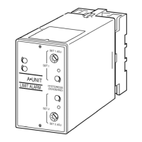
Adjustment for the span setting, typically related to input range or measurement scale.

Zero Adj.

Adjustment for the zero point, used for setting the baseline or minimum value.

No. 1 Setpoint Adj.

Used for adjusting the No. 1 alarm setpoint value.

No. 1 LED

Indicator light that turns on when the No. 1 alarm condition is triggered.

No. 1 Deadband (Hysteresis) Adj.

Adjusts the No. 1 deadband (hysteresis) within a range of 1-100%.

No. 2 Deadband (Hysteresis) Adj.

Adjusts the No. 2 deadband (hysteresis) within a range of 1-100%.

No. 2 LED

Indicator light that turns on when the No. 2 alarm condition is triggered.

No. 2 Setpoint Adj.

Used for adjusting the No. 2 alarm setpoint value.

Installation

DIN Rail Mounting

Instructions for mounting the unit onto a 35mm wide DIN rail using the base socket.

Wall Mounting

Refers to external dimensions for wall mounting guidance, indicating shape and size variations.

Terminal Connections

External Dimensions

Provides detailed physical dimensions of the unit in millimeters and inches for installation planning.

Connection Diagram

Illustrates the wiring connections for input, output, and power terminals.

Terminal Assignments

Details the specific terminal assignments and their physical locations on the unit.

Checking

Terminal Wiring

Verifies correct connection of all cables according to the wiring diagram.

Power Input Voltage

Instructs to check the power input voltage across terminals 7-8 using a multimeter.

Input

Checks if the input signal is within the specified 0-100% of the full-scale range.

Alarm Operations

Guides checking alarm operations by referring to the provided trip operation figure.

Output Load

Checks the output load capacity and recommends external protection for inductive loads.

Maintenance

Calibration

Describes the regular calibration procedure, including warm-up and setpoint adjustments for accuracy.

Lightning Surge Protection

Offers information on lightning surge protectors and advises contacting sales for appropriate model selection.

Adjustment Procedure

Alarm Setpoint and Deadband (Hysteresis)

Details the process for adjusting alarm setpoints and deadband (hysteresis) using simulated input signals.

Related product manuals