TERMINAL CONNECTIONS
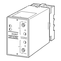
Connect the unit as in the diagram below or refer to the connection diagram on the front of the unit.
When an input resistor is provided with the module, attach it together with input wiring to the input screw terminals.
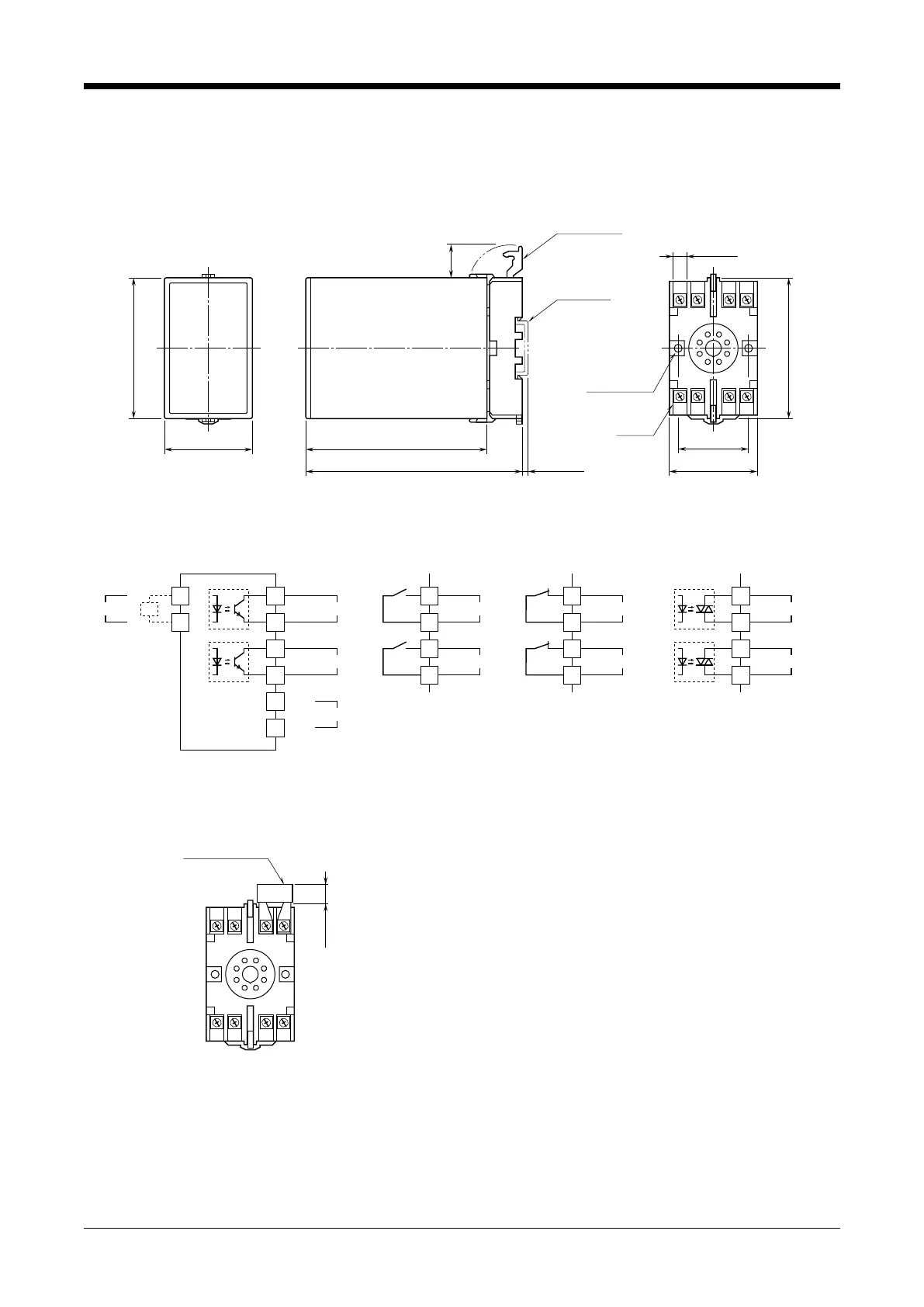
■ EXTERNAL DIMENSIONS unit: mm (inch)
3456
2187
80 (3.15)
50 (1.97) 103 (4.06)
123 (4.84) [3.3 (.13)]
80 (3.15)
20
(.79)
40 (1.57)
50 (1.97)
7.8 (.31)
CLAMP
(top & bottom)
DIN RAIL
35mm wide
2
–
4.5 (.18) dia.
MTG HOLE
15 (.59) deep
8
–
M3.5
SCREW
• When mounting, no extra space is needed between units.
■ CONNECTION DIAGRAM
*Input shunt resistor attached for current input.
+
–
*
INPUT
3
R
4
■ Open Collector
1
2
5
6
7
8
U(+)
V(–)
POWER
LO OUTPUT
HI OUTPUT
2
1
6
5
■ N.O. (make) Relay
HI OUTPUT
LO OUTPUT
■ N.C. (break) Relay
HI OUTPUT
2
1
LO OUTPUT
6
5
■ SSR
HI OUTPUT
2
1
LO OUTPUT
6
5
■ TERMINAL ASSIGNMENTS unit: mm (inch)
56
2187
34
12 (.47)
INPUT RESISTOR
(model: REM)
Input shunt resistor attached
for current input.
AS
EM-1611-A Rev.8 P. 2 / 3
MG CO., LTD. www.mgco.jp
5-2-55 Minamitsumori, Nishinari-ku, Osaka 557-0063 JAPAN