CHECKING
1) Terminal wiring: Check that all cables are correctly con-
nected according to the connection diagram.
2) Power input voltage: Check voltage across the terminal
7 – 8 with a multimeter.
3) Input: Check that the input signal is within 0 – 100% of
the full-scale.
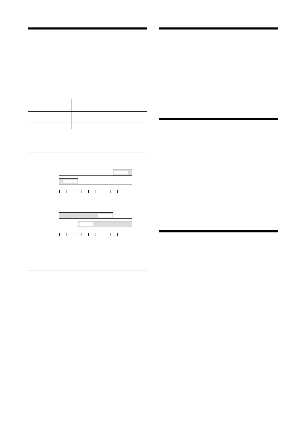
4) Alarm operations: Check the alarm operations referring
to the figure below.
5) Output load: Check the output load corresponds to the
table below.
OUTPUT LOAD RESISTANCE
Open collector 50V DC @100mA
Relay 380V AC @100VA
125V DC @30W
SSR 60 – 280V AC @0.1 – 1A
For maximum relay life with inductive load, external pro-
tection is recommended.
Alarm Trip Operation Terminal No. in parentheses
Trip Operation in Power Failure
• Output Code 1, 2, 4: both relays turn OFF
• Output Code 3: both relays turn ON
05
00▲
Input
(%)
Lo Setpoint
▲
Hi Setpoint
Hi Output
(1–2)ON
Lo Output
(5–6)ON
05
00▲
Input
(%)
Lo Setpoint
▲
Hi Setpoint
Hi Output
(1–2)ON
Lo Output
(5–6)ON
• Output Code 1, 2, 4
• Output Code 3
SETPOINT ADJUSTMENT
Adjustment procedure for the Hi and Lo setpoints are as
follows:
■ HOW TO ADJUST ALARM SETPOINTS
The monitor jacks output 0 – 10V DC in proportion to the
0 – 100% setpoints.
• Hi Setpoint
Measure the voltage at the Hi setpoint monitor jacks and
turn the Hi Adj. until you read a desired value.
• Lo Setpoint
Measure the voltage at the Lo setpoint monitor jacks and
turn the Hi Adj. until you read a desired value.
MAINTENANCE
Regular calibration procedure is explained below:
■ CALIBRATION
Warm up the unit for at least 10 minutes.
• Hi Setpoint
Increase the input signal from a value lower than the set-
point and check that the relay trips at the Hi setpoint
(Measure the voltage at the Hi setpoint monitor jacks).
• Lo Setpoint
Decrease the input signal from a value higher than the
setpoint and check that the relay trips at the Lo setpoint
(Measure the voltage at the Lo setpoint monitor jacks).
When the setpoints are shifted, recalibrate the unit accord-
ing to the “SETPOINT ADJUSTMENT” explained earlier.
When the monitor jacks outputs are shifted, please contact
our sales office or representatives.
LIGHTNING SURGE PROTECTION
We offer a series of lightning surge protector for protec-
tion against induced lightning surges. Please contact us to
choose appropriate models.
AS
EM-1611-A Rev.8 P. 3 / 3
MG CO., LTD. www.mgco.jp
5-2-55 Minamitsumori, Nishinari-ku, Osaka 557-0063 JAPAN
 Loading...