Do you have a question about the MGL Avionics Stratomaster Smart Single and is the answer not in the manual?
Configure aircraft cruising speed for fuel range calculations.
Configure fuel level sender presence and usage.
Calibrate the fuel level sender for tank size and shape.
Details the product warranty period and limitations.
Advice on protecting instruments from voltage transients.
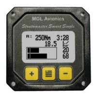
The Stratomaster Smart Single FF-1 is a 2.25" fuel management computer designed for small aircraft, providing efficient monitoring of fuel-related information.
The FF-1 unit offers comprehensive fuel management, including fuel flow, fuel range, fuel endurance, and fuel level. It can connect to a fuel flow sender, a fuel level sender, or both. Full functionality is achieved with both senders, but the unit can also calculate fuel levels based on fuel usage if only a fuel flow sender is connected.
The main display provides real-time information on fuel range, fuel low alarm level, fuel level, fuel endurance (hours:minutes), fuel flow, and remaining fuel.
The device features a menu-driven interface. The Menu key is used to enter the menu, while the + and – keys navigate forward and backward. To select or change an item, highlight it and press the Menu key. Pressing the Menu key again ends an edit or function. To save changes and exit the menu, select the "Done" function.
Users can enter their aircraft's cruising speed, which the FF-1 uses to calculate fuel range based on remaining fuel, current fuel flow, and the entered speed. This value can be adjusted during flight to reflect changes in ground or cruising speed. Caution is advised when using this function to extend range, and a secondary indication of available fuel is always recommended due to potential sender malfunctions.
This function allows manual entry of the current fuel level after fueling or defueling, primarily used when a fuel level sender is not connected or has been disabled. If only a fuel flow sender is used, this initial value is set, and fuel quantity used is subtracted to calculate the current fuel level. It is recommended to account for a "silent" fuel reserve by entering a usable fuel capacity slightly less than the tank's full capacity.
This setting determines whether a fuel level sender is installed. If "No" is selected, the unit relies on the fuel flow sender for fuel level calculations.
This function is crucial for accurate fuel level readings. It allows the system to learn the tank's size and shape, as well as compensate for any errors in the fuel level sender or its installation. Even without a fuel level sender, this function is used to set the tank size. The calibration procedure involves starting with an empty tank, adding fuel in measured increments, and recording the sender's readings at six calibration points (from zero fuel to full tank). The process should be performed with the aircraft in flight attitude (e.g., tail lifted for tail-draggers). A "silent" fuel reserve (at least 10% of tank capacity) should be factored in. The instrument uses these calibration points to create a correction curve, providing an accurate fuel level display. Calibration points can be manually adjusted to fine-tune readings, especially if discrepancies are observed at specific fuel levels. A "Slope error" message indicates an issue with the calibration sequence, such as fuel being removed instead of added between steps.
This function enables or disables the fuel flow sender connection. Most installations will have this set to "yes."
The K-Factor represents the number of pulses generated by the fuel flow sender per liter of fuel. For MGL Avionics' dual-range fuel flow sender, the K-Factor is 7000 in low flow mode (jet installed) and 1330 in high flow mode (no jet installed). Calibration of the fuel flow sender using the K-Factor involves:
Allows users to adjust the display contrast, with selectable values typically ranging from 20 to 45.
Toggles the display backlight on or off.
Users can set a minimum fuel value to trigger a low fuel alarm. When activated, the fuel level display and remaining fuel readout will flash. An external warning lamp can also be connected to the alarm output. This alarm level is displayed as a vertical line on the fuel level display, separate from the "silent" fuel reserve.
Allows selection of preferred units for distance and fuel quantity. Options include:
Warranty: MGL Avionics provides a one-year warranty against faulty workmanship, covering replacement of faulty components and labor costs. Shipping costs are borne by the purchaser. The warranty excludes damages caused by unprotected, unsuitable, or incorrectly wired electrical supplies.
The FF-1 instrument is not certified by the FAA. Its fitting to certified aircraft is subject to local rules and conditions. It is intended for ultralight, microlight, homebuilt, and experimental aircraft. Operation of the instrument is the sole responsibility of the pilot in command (PIC), who must be proficient, hold a valid pilot's license, and be familiar with the instrument's operation and potential failure modes. The manufacturer does not condone its use for IFR flights.
| Brand | MGL Avionics |
|---|---|
| Model | Stratomaster Smart Single |
| Category | Avionics Display |
| Language | English |