DT722 User’s Manual
2 97332 Issue 2, January 2018
INSTALLATION
2 INSTALLATION
2.1 Electrical Connections
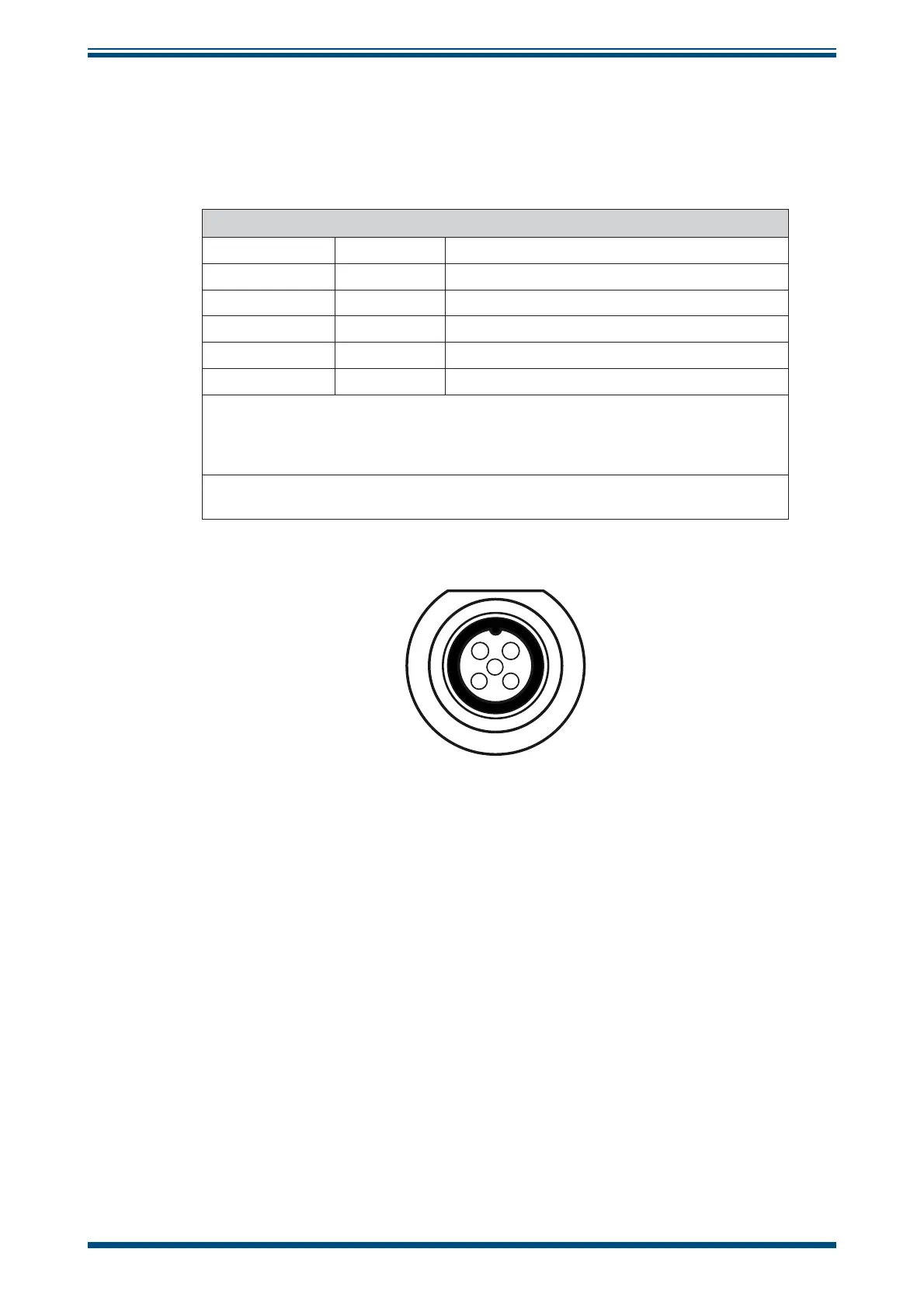
Connections
Cable Pin
White Pin 1 SUPPLY + 8 to 32 V DC
Yellow Pin 2 Output 2 = Temp 4-20 mA (max 500 Ω)
Brown Pin 3 DO NOT CONNECT! (for calibration only)
Green Pin 4 Output 1 = RH 4-20 mA (max 500 Ω)
Pin 5 DO NOT CONNECT! (for calibration only)
NOTE: Even though the DT722 has a 5 pin connector, the standard
connection cable (A000031) has only 4 pins/wires.
However, only 3 pins (1, 2 and 4) are needed to connect the DT722
see
Figure 3
NOTE : Both RH and T need to be connected in order for the T output to
work
1
4
5
2
3
Figure 2
Electrical Connections