Do you have a question about the Michell Instruments Easidew PRO I.S. and is the answer not in the manual?
Safety regarding electrical aspects of the instrument, including options and accessories.
Precautions regarding instrument pressure limits, specifying the safe working pressure.
Information on hazardous materials used in construction and handling precautions during maintenance.
Guidelines for instrument maintenance by the manufacturer or accredited service agents.
Recommended calibration interval of 12 months and procedure for re-calibration.
States product compliance with essential EU directives and applied standards.
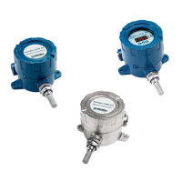
Lists the key features and capabilities of the Easidew PRO I.S. transmitter.
Instructions for checking standard components and handling the instrument upon delivery.
Details on various methods for mounting the transmitter in flow-through sampling blocks or pipes.
Describes the installation procedure for the optional wall-mounting bracket.
Step-by-step guide for mounting the transmitter into a sample block.
Instructions for direct mounting of the transmitter into pipes or ducts.
Guide for installing the transmitter using an adapter for process connections.
Details on preparing and terminating the sensor cable for connection.
Diagram and notes on electrical connections, wiring, and interference reduction.
Information on electrical boundaries and load characteristics graph.
Explains how to configure the transmitter for measurement and output.
Advice on obtaining representative gas samples for accurate measurements.
Details routine calibration procedures and services offered by the manufacturer.
Instructions for replacing the sensor guard and its part number.
Information on replacement bonded seals and how to obtain them.
Provides dimensional drawings for transmitter mounting configurations.
System drawing approved by Baseefa for hazardous area installation.
System diagram approved by FM for installation.
CSA approved system drawing for the transmitter.
Lists product standards the Easidew PRO I.S. conforms to.
Details certification codes for ATEX, IECEx, and North American standards.
Lists various global certificates and approvals obtained.
Specifies electrical terminal parameters for intrinsic safety.
Outlines special conditions for wiring and handling to maintain safety.
Specifies requirements for qualified personnel for maintenance and installation.
| Power Supply | 12 to 28 V DC |
|---|---|
| Operating Temperature | -40 to +60 °C |
| Ingress Protection | IP66 |
| Output Signal | 4-20 mA |
| Hazardous Area Approvals | ATEX, IECEx |
| Measurement Range | -110 to +20 °C dew point |