Easidew PRO I.S. User’s Manual
8 97130 Issue 15, May 2018
INSTALLATION
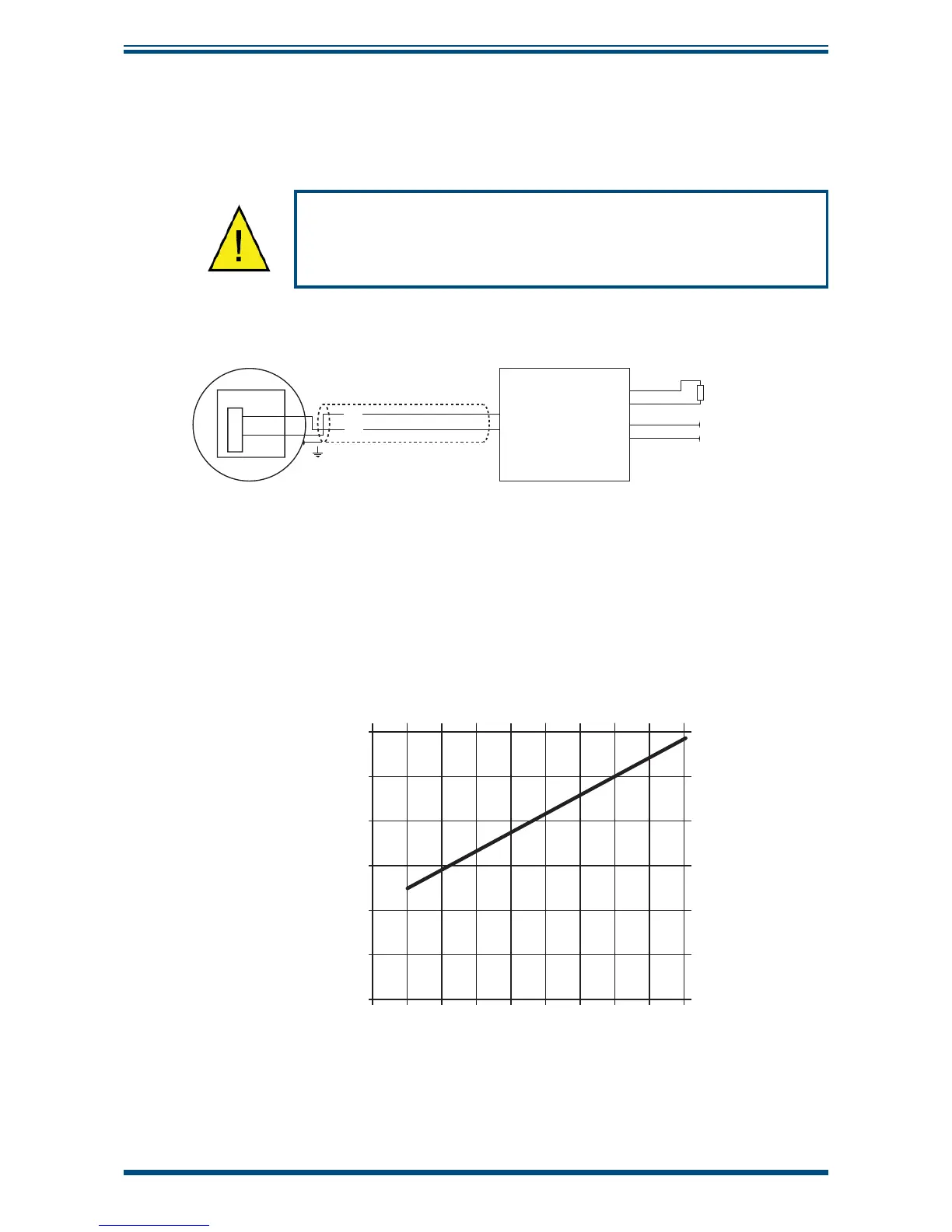
2.4 Electrical Schematic
NOTE: The screen/shield should be connected for maximum performance and
to avoid interference.
Always connect the 4-20 mA return signal to a suitable load
(see
Figure 7)
before the power is applied. Without this
connection, the transmitter may be damaged if allowed to
operate for prolonged periods.
1 2 3 4
SAFE AREAHAZARDOUS AREA
+ 4/20mA
LOAD
+VS (20 to 35 V DC)
VS -
+
-
KFD2-STC4-Ex1 H
KFD0-CS-Ex2.50p
KFD2-CR-Ex1.20200
KFD2-CR-Ex1.30200
KFD0-CS-Ex1.50P
MTL5041
MTL5040
MTL5541
Figure 7
Hazardous Area Connection
1. Connect cable screen to cable gland.
2. Refer to system drawing in Appendix B.
2.4.1 Electrical Boundaries
100
200
300
400
500
600
12 14 16 18 20 22 24 26 28
Resistance (ohms)
Supply Voltage
Figure 8
Maximum Load of Easidew PRO I.S. - Including Cable Resistance