EasyManua.ls Logo

MICO Lock System 691 - User Manual

MICO Lock System 691
24 pages
Print Icon
To Next Page IconTo Next Page
Loading...
Operation and Installation Instructions
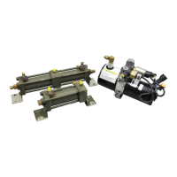
691 LOCK SYSTEM
READ GENERAL INSTALLATION GUIDELINES SHEET (FORM NO. 81-600-001) BEFORE PROCEEDING.
1. The MICO 691 System is a supplemental safety
device which provides additional brake holding
action when used with existing vehicle parking
brake. It is not for dynamic service braking.
2. The 691 System must be used in combination with
an audible and/or visual alarm as a warning to
signal the user of any loss of brake system pres-
sure. Do not disconnect warning devices.
3. All lines, fittings and surrounding areas must be
cleaned of dirt or road residue before any lines or
fittings are disconnected. Special care must be
taken so dirt and road residue are not allowed to
enter the hydraulic brake system. This can con-
taminate the system and interfere with proper
operation of brakes and MICO 691 System.
4. Follow procedures outlined in Vehicle Manufac-
turer’s Service Manual or SAE Standards when
making new connections or adding to existing
brake systems. Use only steel brake tubing con-
forming to SAE specifications.
5. Vehicle Brake System: Always use clean fluid
conforming to vehicle manufacturer’s recommen-
dations. 691 Power Unit: See BEFORE
PROCEEDING, page 3 for proper fluid type.
Improper or contaminated fluid may cause gummy
deposits, softening and swelling of rubber seals,
and may render the 691 System inoperative.
Such a condition must be corrected immediately.
6. Do not use sealants, tapes, teflon or cement
compounds on any connections or fittings. These
sealants or compounds can contaminate the
hydraulic brake system and interfere with the
operation of brake components or MICO 691
System.
7. All fittings and connections must be in good
condition and properly torqued.
8. Brake hoses, brake lines, MICO 691 System,
brake components, cylinders, and all fittings must
be routinely inspected for leaks, damage or wear.
Proper fluid levels must be maintained. In the
event of any loss of fluid, brake system must be
carefully inspected for leaks.
9. When installation of MICO 691 System is com-
plete, 691 System and brake system must be
bled of air. Bleed MICO 691 System according to
procedures outlined in this manual. Bleed brake
system according to vehicle manufacturer’s
recommendations.
10. The self-adhesive warning labels, page 1, ac-
companying each MICO locking device must be
affixed in the vehicle cab in view of operator.
11. Keep this manual in the cab of the vehicle after
installing the 691 System.
MICO is a registered trademark of MICO, Incorporated. MICO is registered in the U.S. Patent and Trademark Office as well as in Australia, Canada, Great Britain, Indonesia, Japan, Peoples Republic of China, and South Korea.
MICO, Incorporated MICO West Division
1911 Lee Boulevard (Zip Code 56003-2507) 701 East Francis Street (Zip Code 91761-5514)
P.O. Box 8118 / North Mankato, MN U.S.A. 56002-8118 P.O. Box 9058 / Ontario, CA U.S.A. 91762-9058
( 507.625.6426 Facsimile 507.625.3212 ( 909.947.4077 Facsimile 909.947.6054
MICO could not possibly know of and give advice with respect to all conceivable applications in which this product may be used and the possible hazards and/or
results of each application. MICO has not undertaken any such wide evaluation. Therefore, anyone who uses an application which is not recommended by the
manufacturer, first must completely satisfy himself that a danger will not be created by the application selected, or by the particular model of our product that is
selected for the application.
MICO has made every attempt to present accurate information in catalogs, brochures and other printed material. MICO can accept no responsibility for errors
from unintentional oversights that may exist. Due to a continuous program of product improvement, materials, specifications, and product documentation are sub
-
ject to change without notice or obligation.
Form No. 81-690-032 Revised Online 11/30/06 Printed in U.S.A.

Questions and Answers

  • K
    Kimberly MckenzieAug 13, 2025
    How to fix a MICO Automobile Parts 691 system power unit that won't release the brakes when deactivated?
    • P
      Patrick HaynesAug 14, 2025
      If the MICO Automobile Parts 691 system power unit doesn't release the brakes when deactivated, check these potential causes: * **No electric power:** Check the battery, fuse, and wiring connections. * **Inoperative low pressure switch:** Deactivate the 691 system. If "PS2" LED is off, replace pressure switch 2 (low pressure switch). * **Inoperative power unit or control module:** Deactivate the 691 System. If the "Motor Down" LED is on, check for 12 VDC at power unit connector. Unplug power unit and attach a voltmeter (- to blue, + to green) to the connector leading to control module. If 12 VDC is present, replace the power unit. If 12 VDC is not present, replace control module.
  • S
    Sara WatersAug 21, 2025
    What causes the MICO Automobile Parts 691 power unit to keep running after the brakes release?
    • K
      Kylie BrownAug 21, 2025
      If the brakes release but the MICO Automobile Parts 691 power unit does not stop running, it could be due to the following: * **Inoperative low pressure switch:** Deactivate the 691 System. If the "PS2" LED is on, replace pressure switch 2 (low pressure switch). * **Inoperative control module:** Deactivate the 691 System. If "Motor Down" LED is off, replace the control module.
  • M
    Mrs. Julia Gross DDSOct 29, 2025
    Why won't the MICO Lock System 691 691 system brakes lock and the power unit not run when activated?
    • M
      Michaela PetersonOct 29, 2025
      There are several potential reasons why the MICO Automobile Parts 691 system brakes won't lock and the power unit doesn't run when activated: * **No electric power:** Check the battery, fuse, and wiring connections. * **Inoperative High Pressure Switch:** Activate the 691 System. If "PS1 (lock)" LED is on, unplug pressure switch 1. If the pump runs, replace pressure switch 1 (high pressure switch) or check for a short to ground in the wiring. * **Inoperative Power Unit or Control Module:** Activate the 691 System. If "Motor Up" LED is on, check for 12 VDC at the power unit connector. Unplug the power unit and attach a voltmeter (+ to blue, - to green) to the connector leading to the control module. If 12 VDC is present, replace the power unit. If 12 VDC is not present, replace the c...
  • C
    Cameron RogersNov 5, 2025
    What to do if MICO Lock System 691 691 system brakes won't lock and the power unit continues to run when activated?
    • E
      Evelyn SanchezNov 6, 2025
      If the MICO Automobile Parts 691 system brakes won't lock and the power unit continues to run when activated, consider the following: * **Low fluid level:** Deactivate the 691 System. Verify that the power unit is mounted level. Remove the reservoir breather/filler plug and fill the reservoir with proper fluid to within 1/4" of top. Reinstall breather/filler plug. * **Hydraulic leak:** Inspect all tubing and connections for leaks and tighten or replace as necessary. * **Actuator malfunction:** Activate the 691 System. Check the vehicle master cylinder reservoir for excessive fluid level. This condition indicates that the seals in the actuator are allowing 691 System fluid to leak into the vehicle service brake system. Replace the seals in the actuator. The vehicle brake system may n...

Summary

INTRODUCTION

The Control Module and User Interface

Describes control module and user interface components.

The Power Unit

Explains function and components of the 691 Power Unit.

The Actuator

Details mechanical actuator linking 691 system to vehicle brakes.

PRINCIPLE OF OPERATION

INSTALLING A 691 SYSTEM

IDENTIFY YOUR BRAKE SYSTEM

DIMENSIONAL DATA

MOUNTING

Actuator

Mounting instructions for the 691 brake system actuator.

Power Unit

Guidance for mounting the 691 Power Unit.

Control Module

Instructions for mounting the 691 Control Module.

User Interface

Details mounting the 691 User Interface in the vehicle cab.

PLUMBING

Single 691 Brake Lock System

Plumbing instructions for single actuator brake lock system.

Dual 691 Brake Lock System

Plumbing instructions for dual actuator brake lock system.

3 Channel Anti-Lock 691 Brake Lock System

Plumbing instructions for 3-channel anti-lock brake systems.

4-Channel Anti-Lock 691 Brake Lock System

Plumbing instructions for 4-channel anti-lock brake systems.

WIRING

691 Wiring Instructions

General instructions and notes for wiring the 691 System.

Connecting External Inputs

How to connect external inputs for 691 System activation.

Connecting the Vehicle Horn

Instructions for wiring the horn warning function.

Connecting Power for the Control Module

Guide to connecting power to the 691 Control Module.

BLEEDING

Tips on Bleeding Brake Systems

Provides advice for effective brake bleeding.

Bleeding Procedures

Step-by-step guide for bleeding the brake system.

Pressure Bleed

Details pressure bleeding methods for the 691 System.

HORN WARNING CIRCUIT TEST

691 OPERATING INSTRUCTIONS

Using 691 as a Lock System

Instructions for operating the 691 system as a lock.

To Deactivate Lock Device

Steps to disengage the 691 lock system.

Using 691 as an Interlock

How to use the 691 system as an interlock.

691 System Installation Checklist

BRAKE LOCK APPLICATIONS

INTERLOCK APPLICATIONS

691 ACCESSORIES

TROUBLESHOOTING

LED Display Explanation

Explains meaning of LEDs on the 691 Control Module.

MICO Lock System 691 Specifications

General IconGeneral
BrandMICO
ModelLock System 691
CategoryAutomobile Parts
LanguageEnglish