4
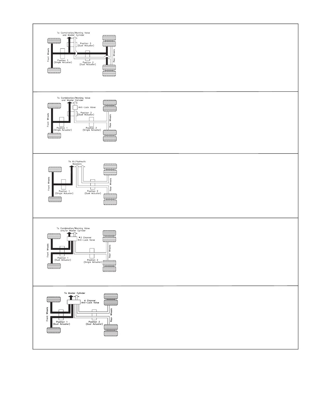
Typical Split System (1 1/2 x 1/2)
Two independent braking systems. One system leads to the front and the rear
brakes and the other system leads only to the rear brakes.
Identifying Feature:
1.Two lines from master cylinder.
2.Single hose to each front wheel.
3.Two hoses to rear axle.
691 Actuator Position:
(1) Front axle (2) Rear axle (3) 4-wheel
CAUTION: Whether position 2 or 3 is used, both halves of system must be
locked.
FIGURE 7
FIGURE 8
Typical 3-Channel All-Wheel Anti-Lock System
Provides braking control by way of independent anti-lock channels for each front
wheel and a third channel for both rear wheels.
Identifying Feature:
1.Two lines from master cylinder to anti-lock valve(s).
2.One line from anti-lock valve to rear brakes.
3.Separate lines from anti-lock valve to each front wheel.
691 Actuator Position:
(1) Front axle (2) Rear axle (1 & 2) 4-wheel
NOTE: Some 3-channel anti-lock brake systems use two separate anti-lock
valves.
FIGURE 10
Typical 4-Channel All-Wheel Anti-Lock System
Provides braking control by way of an independent channel for each front wheel
and each rear wheel.
Identifying Feature:
1.Two lines from master cylinder to anti-lock valve.
2.Separate lines from anti-lock valve to each of the front and rear wheels.
691 Actuator Position:
(1) Front axle (2) Rear axle (1 & 2) 4-wheel
NOTE: Some 4-channel anti-lock brake systems use two separate anti-lock
valves.
FIGURE 11
Imported Truck 3-Channel All-Wheel Anti-Lock System
Provides braking control by way of independent anti-lock channels for each rear
wheel and a third channel for the front wheels.
Identifying Feature:
1.Three separate air/hydraulic brake boosters.
2.One line to front brakes.
3.Separate lines to each rear wheel.
691 Actuator Position:
(1) Front axle (2) Rear axle (1 & 2) 4-wheel
NOTE: The anti-lock functions on air booster system, not the hydraulic side.
FIGURE 9
Typical Rear Wheel Anti-Lock System
(Dual Vertical Split)
Two independent braking systems. One system leads to the front brakes and the
other system to the rear brakes.
Identifying Feature:
1.Two lines from master cylinder.
2.Anti-lock control valve between master cylinder and rear wheels.
691 Actuator Position:
(1) Front axle (2) Rear axle (3) 4-wheel